Notifier FZM-1 Interface Module

File Preview
Click below to download for free
Click below to download for free
File Data
| Name | notifier-fzm-1-interface-module-8972461053.pdf |
|---|---|
| Type | |
| Size | 496.31 KB |
| Downloads |
Text Preview
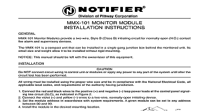
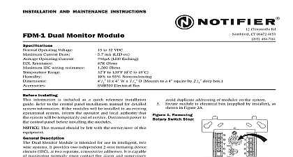
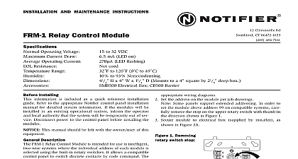
INSTALLATION AND MAINTENANCE INSTRUCTIONS Clintonville Rd Northford CT 06472 1653 484 7161 Interface Module Operating Voltage 15 to 32 VDC Current Draw 5.1 mA LED on Operating Current 270 LED flashing Resistance 3.9K Ohms IDC wiring resistance 25 Ohms Supply Voltage between Terminals T3 and T4 DC Voltage 18 28 volts power limited 19 to 28VDC when used with MTL isolator model MTL3043 in intrinsically safe applications Ripple Voltage 0.1 Volts RMS maximum Current 90mA per module Range 32 to 120 0 to 49 10 to 93 Noncondensing 41 SMB500 Electrical Box D Mounts to a 4 square by 21 H x 4 W x 11 deep box Installing information is included as a quick reference installa guide Refer to the control panel installation manual detailed system information If the modules will be in an existing operational system inform the and local authority that the system will be tempo out of service Disconnect power to the control panel installing the modules Install module wiring in accordance with the job draw and appropriate wiring diagrams Set the address on the module per job drawings Note Some panels support extended addressing In to set the module above address 99 on compatible carefully remove the stop on the upper rotary with thumb in the direction shown in Figure 1 Secure module to electrical box supplied by installer This manual should be left with the owner user this equipment Description FZM 1 Interface Module is intended for use in intel two wire systems where the individual address of module is selected using the built in rotary switches module allows intelligent panels to interface and moni two wire conventional smoke detectors It transmits the normal open or alarm of one full zone of con detectors back to the control panel All two wire being monitored must be UL compatible with this The FZM 1 has a panel controlled LED indicator can be used to replace an MMX 2 module in existing Requirements ensure proper operation this module shall be connected a compatible Notifier system control panel only list from Notifier FZM 1 mounts directly to 4 square electrical boxes see 2A The box must have a minimum depth of 21 mounted electrical boxes SMB500 are available Notifier All wiring must conform to applicable local codes and regulations This module is intend for power limited wiring only shown in Figure 2A 1 Removing Switch Stop 865 6 7 8 9 2A Module mounting 2B 10 2 1 9 10 2 1 9 1 I56 1172 06 3 Interface two wire conventional NFPA Style B WIRING MUST BE POWER LIMITED NOT MIX FIRE ALARM INITIATING SUPERVISORY SECURITY DEVICES ON THE SAME MODULE EOL LINE VDC MAX PAIR RECOMMENDED MODULES TO LISTED CONTROL PANELS ONLY PANEL OR DEVICE NEXT 865 6 7 8 9 BATTERY BACKUP SWITCHED POWER SUPPLY TO THE INTERFACE MODULE BE EXTERNALLY SWITCHED TO THE DETECTORS AN FRM 1 CONTROL MODULE CAN BE USED TO POWER FROM A STANDARD SUPPLY SEE FIGURE 5 NOT LOOP WIRE UNDER TERMINALS BREAK WIRE TO PROVIDE SUPERVISION OF CONNECTIONS MUST BE UL LISTED COMPATIBLE WITH MODULE DETECTORS PER MANUFACTURER S INSTRUCTIONS BRANCH CIRCUIT NEXT INTERFACE MODULE SUPERVISES SUPPLY AND DETECTOR LOOP 4 Interface two wire conventional NFPA Style D 5 Relay control module to disconnect a power supply WIRING MUST BE POWER LIMITED NOT MIX FIRE ALARM INITIATING SUPERVISORY SECURITY DEVICES ON THE SAME MODULE LINE MODULES VDC MAX PAIR RECOMMENDED LISTED COMPATIBLE PANELS ONLY PANEL PREVIOUS NEXT LINE VDC MAX PAIR RECOMMENDED MODULES LISTED COMPATIBLE PANELS ONLY OR NEXT 865 6 7 8 9 EOL RESISTOR AT TERMINALS 9 INCLUDED BATTERY BACKUP DC POWER SUPPLY TO THE INTERFACE MODULE BE EXTERNALLY SWITCHED TO THE DETECTORS AN FRM 1 CONTROL MODULE CAN BE USED SWITCH POWER FROM A STANDARD SUPPLY SEE FIGURE 5 NOT LOOP WIRE UNDER TERMINALS BREAK WIRE TO PROVIDE SUPERVISION OF CONNECTIONS MUST BE UL LISTED COMPATIBLE WITH MODULE DETECTORS PER MANUFACTURER S INSTRUCTIONS BRANCH CIRCUIT NEXT INTERFACE MODULE SUPERVISES SUPPLY AND DETECTOR LOOP 6 Interface two wire intrinsically conventional detectors NFPA Style B WIRING MUST BE POWER LIMITED NOT MIX FIRE ALARM INITIATING SUPERVISORY SECURITY DEVICES ON THE SAME MODULE LIMITED POWER SUPPLY FOR FIRE BATTERY LINE VDC MAX PAIR RECOMMENDED MODULES TO LISTED CONTROL PANELS ONLY PANEL OR DEVICE NEXT 865 6 7 8 9 BATTERY BACKUP SWITCHED POWER SUPPLY EOL NOT LOOP WIRE UNDER TERMINALS BREAK WIRE TO PROVIDE SUPERVISION OF CONNECTIONS MUST BE UL LISTED COMPATIBLE WITH MODULE DETECTORS PER MANUFACTURER S INSTRUCTIONS ISOLATOR BRANCH CIRCUIT NEXT INTERFACE MODULE SUPERVISES SUPPLY AND DETECTOR LOOP 2 I56 1172 06 Notifier TO THE INTERFACE MODULE BE EXTERNALLY SWITCHED TO THE DETECTORS AN FRM 1 CONTROL MODULE CAN BE USED TO POWER FROM A STANDARD SUPPLY SEE FIGURE 5