Notifier MDL Module – for SpectrAlert series of horns strobes
File Preview
Click below to download for free
Click below to download for free
File Data
| Name | notifier-mdl-module-for-spectralert-series-of-horns-strobes-8367245910.pdf |
|---|---|
| Type | |
| Size | 1.02 MB |
| Downloads |
Text Preview
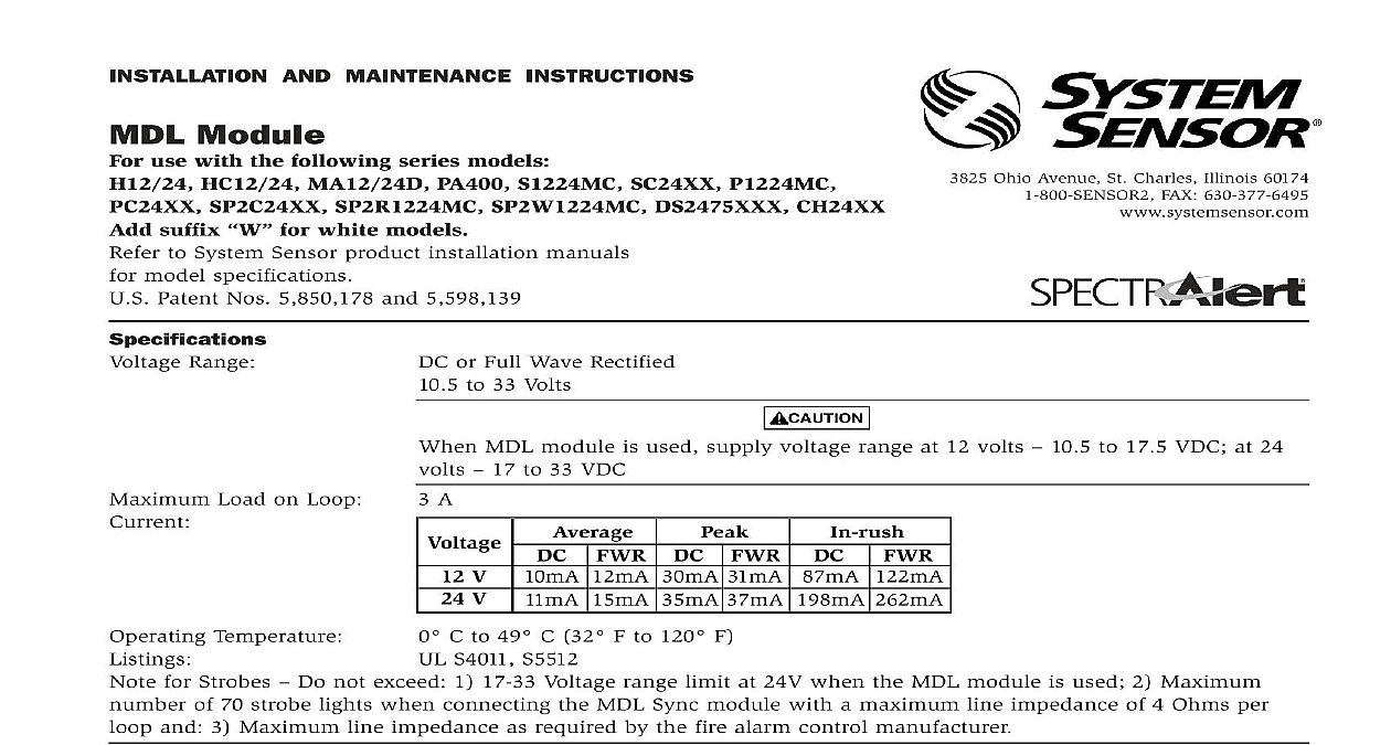
INSTALLATION AND MAINTENANCE INSTRUCTIONS Module use with the following series models HC12 24 MA12 24D PA400 S1224MC SC24XX P1224MC SP2C24XX SP2R1224MC SP2W1224MC DS2475XXX CH24XX suffix for white models to System Sensor product installation manuals model specifications Patent Nos 5,850,178 and 5,598,139 Range DC or Full Wave Rectified 10.5 to 33 Volts 3825 Ohio Avenue St Charles Illinois 60174 FAX 630 377 6495 When MDL module is used supply voltage range at 12 volts 10.5 to 17.5 VDC at 24 17 to 33 VDC Load on Loop 3 A V V DC FWR 12mA 30mA 31mA 87mA 122mA 15mA 262mA 37mA Temperature 0 C to 49 C 32 F to 120 F UL S4011 S5512 for Strobes Do not exceed 1 17 33 Voltage range limit at 24V when the MDL module is used 2 Maximum of 70 strobe lights when connecting the MDL Sync module with a maximum line impedance of 4 Ohms per and 3 Maximum line impedance as required by the fire alarm control manufacturer Description MDL Module is designed to work with the SpectrAlert of horns strobes and horn strobes to provide a of synchronizing the Temporal coded horns syn the one second flash timing of the strobe and the horns of the horn strobe combination over a circuit while leaving the strobes active This manual shall be left with the owner user of equipment Configuration MDL module has the capability of connecting two Y Class B circuits or one Style Z Class A circuit zone output s from the panel are connected to the inputs of the MDL module and the zone output s the MDL module are connected to the notification Supervision is accomplished in the module by a connection between the zone input and the zone of each of the two zone circuits connected to the end of line device The FACP the EOL device the MDL module When either or both outputs the module are wired to the SpectrAlert products the and strobes in both zones will be synchronized MDL module can be configured so that more than two can be synchronized by the interconnection of the input and output see Figures 1 and 2 1 Input This input powers the MDL module This must have voltage present from the FACP anything will work This also supplies to Zone 1 output 2 Input This input only supplies voltage to Zone 2 Note If Zone 1 input is not powered notification devices attached to the Zone 2 will not be powered Control This input enables the horns on the SpectrAlert appliances Voltage present means are enabled No voltage present means are disabled In Connects to Master MDL Module slave out Out Connects to Slave MDL slave in 1 I56 0983 013 SpectrAlert Horns and Strobes Each module can power two 3 amp circuits wired in B or one 3 amp circuit powered as Class A Each module will synchronize 2 zones Additional modules can be added and may be syn to all other modules by interconnecting the input and output terminals between modules control wiring must be contained within common of module Out Slave In wiring must be contained within either common enclosure of modules or enclosures within 20 of each other with wiring inside conduit Zone 1 input is not powered or fails during alarm the devices attached to the Zone 2 output will not powered Sounder On Off Over 2 Wires Using Horn Control Connect the current source to the horn control input If zone output is used for the source you must use an on the horn control input terminal When multiple modules are used the horn control cir can be wired in parallel If wired in parallel and a output is used from panel use an EOL on the last for supervision control wiring must be contained within common of module Out Slave In wiring must be contained within either common enclosure of modules or enclosures within 20 of each other with wiring inside conduit Zone 1 input is not powered or fails during alarm the devices attached to the Zone 2 output will not powered Considerations latching Relay contact is provided in case the synchro signal to the notification devices is interrupted The can be wired so that a trouble signal will be annun at the panel If the synchronization pulse fails in the module the strobes will shut off 1 If zone 1 output of module is connected to strobes horn strobes zone 1 input supply power must continuous for proper operation Z A OUT RETURN MODULE 1 1 2 2 Jumper Off MODULE 1 1 2 2 Jumper Off NEXT OR NEXT OR STYLE Y CLASS B SpectrAlert horns and strobe devices will in sync STYLE Z CLASS A NEXT OR NEXT OR The panel or FACP must be capable of providing Style Z Class A or NAC circuitry Consult with panel manufacturer 2 If zone 1 output of module is connected to strobes horn strobes zone 1 input supply power must continuous for proper operation SILENCED OVER TWO WIRE CIRCUIT MODULE HORN CONTROL CONNECTS INTERRUPTABLE POWER SOURCE MODULE 1 1 2 1 2 2 JUMPER OFF MODULE 1 1 2 2 JUMPER OFF NEXT OR NEXT OR NEXT OR NEXT OR SpectrAlert horns and strobes operate in sync 2 I56 0983 013 The MDL Module is factory set with the sync error in the open state These contacts may during shipping Approximately two seconds power up these contacts will open This contact could be wired to a separate monitor input at FACP 3 Single MDL Using Sync Error If zone 1 output of module is connected to strobes horn strobes zone 1 input supply power must continuous for proper operation CODE OUT 5 Wiring for Coded Supplies SPECTRALERT STROBE ONLY NEXT EOL NEXT POWER EOL