Notifier MPS-24 AVPS-24 PS Product Repair Instructions

File Preview
Click below to download for free
Click below to download for free
File Data
| Name | notifier-mps-24-avps-24-ps-product-repair-instructions-8719354062.pdf |
|---|---|
| Type | |
| Size | 956.56 KB |
| Downloads |
Text Preview
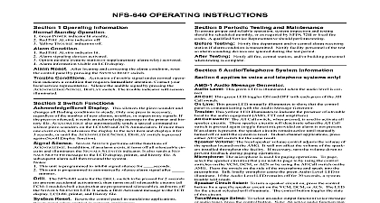
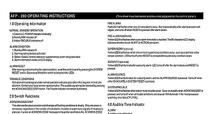
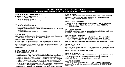
Product Repair Instructions for the MPS 24 AVPS 24 Power Supplies the following instructions for repair of MPS 24 or AVPS 24 power supplies that may have a defective PTC component Verify the fire alarm system has the defective component Systems which may exhibit this problem include AM 2020 AFP XP System 5000 System 2500 Sensiscan 2000 or System 500 models which were shipped from Notifier Fire May 1991 and January 15 1992 Only those systems which use the MPS 24 MPS 24E MPS 24F AVPS 24 AVPS or AVPS 24F modules may have the problem MPS 24A or MPS 24B series power supplies are not affected defective part is a particular PTC Positive Temperature Coefficient resistor which is used for power limiting and as a self restoring fuse It limits the power for unregulated DC indicating appliances Although rated for 3.75 amperes component may activate after 2 to 10 minutes if the load current exceeds 2.0 amperes causing a shutdown of any appliances or other output devices connected to the system This component is a yellow disk marked located on the power supplies as shown below On the enclosed replacement board the non defective part is with the same number but is noticeably thicker Notify the local fire department building owner and other local authorities of the plan to temporarily disconnect the alarm system for service Shut off main AC power to the system Disconnect all batteries connected the MPS 24 or AVPS 24 power supplies Remove all wires and cables connected to the PC board on the MPS 24 or AVPS 24 power supplies If necessary Remove 7 screws from the MPS 24 or 4 screws from the AVPS 24 as shown above Set the screws aside for later re the wires to aid re installation Remove the PC board and replace with the board supplied by this kit Install the screws Connect all wires and cables in their original position on the PC board Do not yet connect the batteries Apply AC power to the system Connect the batteries Test the system especially the power supply outputs Notify all authorities that the fire alarm system is again operational Package the board with the defective PTC in the carton used with this kit to Alarms Alarms Alarms Alarms Alarms Department Department Department Department Department Clintonville Rd Clintonville Rd Clintonville Rd Clintonville Rd Clintonville Rd CT 06472 CT 06472 CT 06472 CT 06472 CT 06472 15098 A 2 4 92