Notifier NBG-12 Series Manual Pull Stations

File Preview
Click below to download for free
Click below to download for free
File Data
| Name | notifier-nbg-12-series-manual-pull-stations-0152947863.pdf |
|---|---|
| Type | |
| Size | 1.38 MB |
| Downloads |
Text Preview
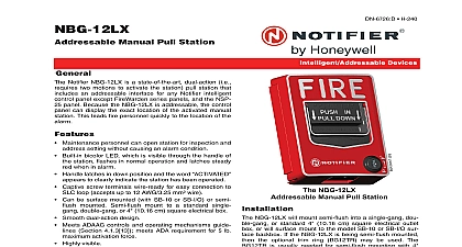
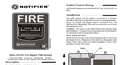
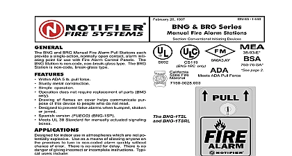
Switch Contact Rating switch contacts are rated for 0.25 A at 30 volts AC or DC mount the NBG 12 pull station to a SB 10 surface backbox mount the NBG 12 to a standard single gang double or 4 inch 10.16 cm square electrical box Mount the Trim Ring BG TR if necessary when semi flush mounting unit word displayed the pull station handle during mounting of the pull station the door becomes de complete the following steps to reattach the door to the The door cannot be connected to the pull station if the is mounted to the backbox Position the door and backplate side by side in the full open i e 180 degrees with respect to each other With the backplate position fixed move the door behind the as shown in the illustration part A Align the hinge posts and holes by bringing the door up to meet backplate paying particular attention to the that when the door post hole is aligned to the backplate post Refer to the illustration part B With the two pieces aligned and together slide the holes onto the posts Refer to the illustration part C Holding the backplate close the door slightly to lock the door backplate together INTO AT THIS POINT ATTACHMENT the door and aligned and together slide holes down onto posts 50997 REV TO DOCUMENT 51015 REV the door slightly the door and together 50997 REV TO DOCUMENT 51015 REV MATED TO BACKPLATE Action NBG 12L Series Manual Pull Stations Document 51015 Revision B2 ECN 03 126 03 13 03 Patents D428,351 6,314,772 6,380,846 NBG 12 Series Pull Stations are non coded manual pull which provide a Fire Alarm Control Panel FACP a single alarm initiating input signal The NBG 12 includes both single action and dual action models with either a hex or key lock reset A single action is activated by a single pull down of the alarm The dual action versions require pushing in the then pulling the handle down for activation The series manual pull stations are UL listed and meet the requirement of a 5 lb maximum pull force to activate instructions are molded into the handle along with text Molded terminal numbers can be found adjacent the wiring terminals Series Models available Single action with connections and hex lock reset Pigtail wires are provided for connec to the Fire Alarm Control Panel FACP Initiating Circuit IDC Dual action model with screw terminal and a hex lock reset Same as NBG 12 except with a key lock reset Same as NBG 12L except with both and Spanish operating instructions Black in out in FACP FACP Next Device Next Addresable Device GAUGE GAUGE Action NBG 12S Action NBG 12L Activated Action NBG 12S Pigtails Action NBG 12 12L Wiring Do not loop wiring under any terminals Break wire run to maintain IDC supervision Instructions for the NBG 12 NBG 12L and NBG 12LSP semi flush mounting proceed to step 4 Mount the backbox before wiring to the pull station Before mounting the station pull all necessary wiring through the backbox and optional BG TR Remove the correct amount of wire insulation The pull station backplate is molded with a strip gauge to measure the of insulation to be removed Connect the wiring from the fire alarm control panel IDC or any previous device on the IDC to terminals 1 and 2 on the stations terminal strip Connect the next device on the IDC or End of Line Resistor ELR to terminals 1 and 2 Maintain consistent polarity with all connections throughout the IDC Instructions for the NBG 12S instructions 1 through 3 above then proceed with steps 4 and 5 following Connect the field wiring from the FACP IDC or the previous device on the IDC to the pull station Connect positive IDC wire to a red pigtail and the negative IDC wire to a black pigtail Next connect the positive going to the next device or an ELR to the remaining red positive Connect the negative wire going to next device or an ELR to the remaining black negative pigtail Maintain consistent polarity with all connections throughout the IDC activate a single action pull station simply pull down the handle To activate dual action stations push in pull down the handle The word apears after the handle is pulled down The pull station in the activated position until reset To reset the NBG 12S and NBG 12 hex lock pull stations work the supplied 9 64 inch hex wrench into the until firmly seated and turn counterclockwise 1 4 turn reset the NBG 12L and NBG 12LSP key lock stations insert the key and turn counterclockwise 1 4 turn Open the door until the handle returns to the position Close and lock the door Closing the door automatically resets the switch to the position Opening the pull station door will not activate or deactivate the alarm switch BG 12 hex wrench must be fully seated work properly the pull station in accordance with the supplied instructions applicable NFPA standards national and local Fire and Electrical and the requirements of the Authority Having Jurisdiction AHJ Conduct regular testing of the devices using appropriate NFPA Notifier is not responsible for devices that have not been properly installed tested or maintained ADA compliance if the clear floor space only allows forward approach to an object the maximum forward reach height allowed is inches 121.92 cm If the clear floor space allows parallel approach by a person in a wheelchair the maximum side reach height allowed 54 inches 137.16 cm Document 51015 Revision B2 ECN 03 126 03 13 03 de Contacto del Interruptor los contactos de interruptor son clasificados para 0.25 A en 30 AC o DC en la superficie la estaci NBG 12 a una caja posterior de superficie Instale semi empotrada la NBG 12 a una caja el cuadrada de 10.16 cm de grupo doble o singular Instale el Anillo Embellecedor si es necesario cuando la unidad est siendo semi empotrada palabra mostrada el manubrio de hale la estaci mientr se instalando la estaci la puerta se separa complete los pasos para unir la puerta a la placa posterior La puerta no puede conectada a la estaci pulsadora si la unidad est instalada en la caja Coloque la puerta y la placa posterior de lado a lado en la posici de completo es decir 180 grados con respecto la una a la otra Con la placa posterior fijada en lugar mueva la puerta detr de la placa como es mostrado en el dibujo debajo parte A Al los postes y orificios de la bisagra juntando la puerta con la placa poniendo atenci a como las piezas caen en su lugar cuando orificos de la puerta son alineados con los postes de la bisagra de la posterior Refi al dibujo parte B Con las dos piezas alineadas y juntas deslize los orificios hacia abajo de los postes Refi al dibujo parte C Agarrando la placa posterior una la puerta y la placa posterior para DE LA PUERTA la puerta y la tapa alineados jun abajo hacia postes 50997 REV TO DOCUMENT 51015 REV la puerta un asegura la puerta la tapa tracera juntos 50997 REV puerta ahora es a la placa ORIFICIO dentro del en la Puerta de Doble Acci Pulsadoras Man