Notifier ONYX® Series DPI-232 Direct Panel Interface
File Preview
Click below to download for free
Click below to download for free
File Data
| Name | notifier-onyx-series-dpi-232-direct-panel-interface-1874506923.pdf |
|---|---|
| Type | |
| Size | 732.47 KB |
| Downloads |
Text Preview
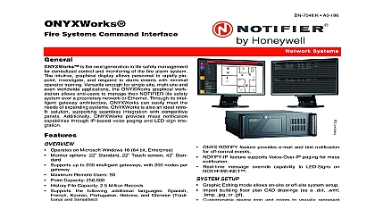
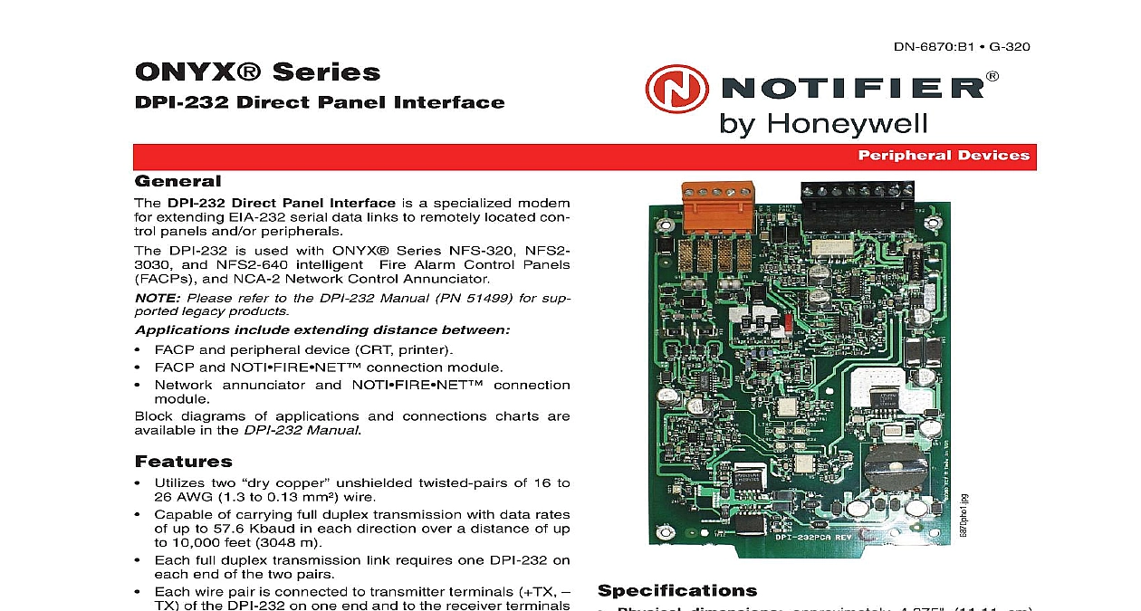
ONYX Series Direct Panel Interface DPI 232 Direct Panel Interface is a specialized modem extending EIA 232 serial data links to remotely located con panels and or peripherals DPI 232 is used with ONYX Series NFS 320 NFS2 and NFS2 640 intelligent Fire Alarm Control Panels and NCA 2 Network Control Annunciator Please refer to the DPI 232 Manual PN 51499 for sup legacy products include extending distance between FACP and peripheral device CRT printer FACP and NOTI connection module Network annunciator and NOTI connection diagrams of applications and connections charts are in the DPI 232 Manual Utilizes two copper unshielded twisted pairs of 16 to AWG 1.3 to 0.13 mm wire Capable of carrying full duplex transmission with data rates up to 57.6 Kbaud in each direction over a distance of up 10,000 feet 3048 m Each full duplex transmission link requires one DPI 232 on end of the two pairs Each wire pair is connected to transmitter terminals TX of the DPI 232 on one end and to the receiver terminals of the DPI 232 on the other end Each DPI 232 supervises for ground faults on the wire pair to TX and terminals The ground fault has an LED indicator as well as Form C trouble Panel peripheral terminals are electrically isolated from the pair terminals Equipped with a power saving switch that allows power at the lower data rates of up to 9,600 baud data rates than 9,600 baud require setting switch to Plugs into a 120 VAC wall outlet and supplies 24 VDC to the DPI 232 modem This power supply must be when the modem is not being powered directly from a or other UL Listed power limited power supply Listed fire protective signaling G 320 Devices Physical dimensions approximately 4.375 11.11 cm by 6.875 17.30 cm high Mounts onto any panel location Temperature and humidity ranges This system meets requirements for operation at 0 to 49 32 to and at a relative humidity noncondensing of 85 30 86 per NFPA and 93 2 at 32 2 1.1 per ULC However the useful life of the standby batteries and the electronic components be adversely affected by extreme temperature ranges humidity Therefore it is recommended that this system all peripherals be installed in an environment with a room temperature of 15 to 27 60 to 80 voltage range 18.0 to 31.0 VDC 24 V nominal Power requirements 245 mA with SW1 set to 148 with SW1 set to Performance and capacity per NFPA SLC classification Style 4 for data rates up to 9600 baud Style 3.5 for data rates up to 57.6 Kbaud Distance limitations Up to 10,000 feet 3,048 m on 16 to 24 AWG 1.3 to 0.2 unshielded twisted pair wire whichever the above comes first Up to 580 ohm total 290 ohm each wire of wire resis Wiring from the DPI 232 that is installed outside the Cannot exceed 1,000 meters 3,280 feet 03 27 2012 Page 1 of 2 approval agencies or listing may be in process Con factory for latest listing status UL Canadian and non Canadian S635 Listed MEA 253 02 E CSFM 7300 0028 0222 7165 0028 0224 7170 0028 0243 NFS2 640 NFS 320SYS City of Chicago approved Class 1 Class 2 City of Denver approved FDNY COA 6085 6098 Line Information Direct Panel Interface modem for extending EIA 232 data links Must be in conduit Cannot cross any power lines Mounting The DPI 232 is designed to mount in CHS M2 or CHS 4L chassis or on the ADP 4B annuncia dress panel Refer to the DPI 232 Manual for further and diagrams Highlights LEDS Power green LED 1 illuminates to indicate presence of power RX Line green LED 2 illuminates when the RX line is con to the receiver with proper polarities RX 232 LED 3 when RX Line LED 2 above is illumi RX 232 LED 3 illumination indicates data is being TX 232 LED 4 when TX Line LED 5 below is illumi TX 232 LED 4 illumination indicates data is being TX Line green LED 5 illuminates when the TX line is con to the receiver with proper polarities Earth Fault yellow LED 6 illuminates when a ground fault detected on the twisted pair connected to the transmitter AND CONNECTIONS SW1 Power Save switch has two settings and Data rates above 9,600 baud require setting the to position Set the switch to to con energy for data rates up to 9,600 baud TB1 TB2 TX TX connections to remote device for use 16 26 AWG 1.3 to 0.13 mm twisted pair wire Earth connect to ground of cabinet chassis RX RX connections to remote device for use 16 26 AWG 1.3 to 0.13 mm twisted pair wire EIA 232 TX connection to EIA 232 TX con of panel peripheral EIA 232 REF connection to EIA 232 REF of panel peripheral EIA 232 RX connection to EIA 232 TX con of panel peripheral Earth Flt NO NC C normally open NO normally NC and common C earth fault trouble contacts 24V connection to listed 24 VDC power source Common connection to 24 VDC common NUP EIA 232 cable connection for NUP network cable NUP compatible equipment Listings and Approvals listings and approvals apply to the DPI 232 In some certain modules or applications may not be listed by is a trademark and ONYX and UniNet are registered of NOTIFIER NION is a registered trademark of Honeywell Inc and FlashScan are registered trademarks of Honeywell Inc by Honeywell International Inc All rights reserved Unauthorized use document is not intended to be used for installation purposes We try to keep our product information up to date and accurate cannot cover all specific applications or anticipate all requirements specifications are subject to change without notice more information contact Notifier Phone 203 484 7161 FAX 203 484 7118 in the U S A 2 of 2 DN 6870 B1 03 27 2012