Notifier ONYX Series NCA Network Control Annunciator

File Preview
Click below to download for free
Click below to download for free
File Data
| Name | notifier-onyx-series-nca-network-control-annunciator-5816290374.pdf |
|---|---|
| Type | |
| Size | 1.71 MB |
| Downloads |
Text Preview
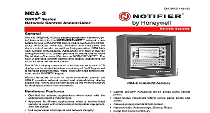
ONYX Series NCA Control Annunciator NOTIFIER Network Control Annunciator NCA is a 640 backlit LCD display with operator keypad for the network As a remote node on a network it both system control and display capabilities for all nodes NCA is an optional display for the ONYX Series NFS and NFS 640 control panels When mounted in the con cabinet and connected to a stand alone NFS 3030 or panel it provides system control and display capabil for a stand alone panel When connected to a networked as a primary display it can provide network control and display capabilities Features Full supervision of all inputs and network integrity Enhanced format 640 character LCD display with backlight ACS bus for LED or graphic annunciators EIA 485 Terminal bus for mimic annunciators EIA 485 Optically isolated Printer CRT interface EIA 232 Keyboard interface EIA 232 Ten LED status indicators Power Fire Alarm Pre Alarm Security Alert Supervisory Signal Silence CPU Failure Point Disabled Other Alphanumeric QWERTY rubber keypad with tactile and Four status relays Alarm Trouble Supervisory Security feedback Nonvolatile real time clock can be synchronized with net by master node Optional Security Keyswitch enable to NCA Optional Security Tamper switch Supports up to 32 remote ACS annunciators and modules Requires 24 VDC and either a network connection or a connection to the NFS 640 or NFS 3030 Enable Disable or Group Enable Disable local networked NFS 640 NFS 3030 points and zones Control ON OFF of local the panel in the same cabinet networked NFS 640 NFS 3030 control points Read Status of local the panel in the same cabinet and NFS 640 NFS 3030 points and zones Network event display and optional CRT with keyboard Network master fire phone paging control HVAC control Network wide Acknowledge Silence Reset Lamp Test local to NCA History Buffer 200 Alarm events 1,000 System events Print NCA programming and history reports Report status of networked panels and their respective field to a central station via a single UDACT see data DN 4867 A0 120 Systems in ABF 2DB as NFS 640 in sized cabinet with and system One Master level and nine User level passwords The Mas can assign each User access levels programming alter Summary Event Count display event handling Online programming and alter status programs user guidance program including interactive soft Enhanced Read Status Alter Status displays New history filters for report displaying and printing All Only Alarms Only Troubles Only Supervisory Only Time Interval Point Range Fully programmable node mapping subsystem New Advanced Basic Walk Test program Timer control for Auto Silence AC Fail Delay Meets Canadian ULC display requirements Environmental adjustment controls to maximize LCD legibil Meets NFPA requirements for Firefighter Smoke Control FSCS and HVAC Indicators and Controls INDICATORS Power green illuminates when 24 VDC power is applied goes out if power is removed and NCA is using a bat Fire Alarm red illuminates when at least one fire alarm exists flashes when any of these events remain 11 16 06 Page 1 of 4 Pre Alarm yellow illuminates when at least one pre alarm Number for future use and humidity ranges This system meets requirements for operation at 0 to 49 32 to and at a relative humidity noncondensing of 85 at 86 per NFPA and 93 2 at 32 2 89.6 per ULC However the useful life of the system batteries and the electronic components may be affected by extreme temperature ranges and humid Therefore it is recommended that this system and all be installed in an environment with a nominal room of 15 to 27 60 to 80 REQUIREMENTS NCA may be powered from a Main Power Supply MPS MPS 24AE MPS 24B or MPS 24BE mounted in the cabinet see specifications below from an ACPS 2406 supply see ACPS 2406 data sheet DN 6834 or from UL Listed non resettable 24 VDC source from a NOTI fire panel see panel data sheets battery on the NCA motherboard is for RTC and SRAM the history memory through power failure Replace are available LITHBATT 3V power MPS 24A MPS 24B 120 VAC 50 60 Hz 1.8 maximum MPS 24AE MPS 24BE 220 240 VAC 50 60 0.9 amps maximum power MPS 24A MPS 24AE 27.6 VDC 9 to 60 supervised and power limited Fast charge 2 amps charge 20 mA MPS 24B MPS 24BE 27.6 VDC 6.5 17 AH supervised and power limited Fast charge 750 maximum trickle charge 20 mA typical Listings and Approvals listings and approvals apply to the NCA In some cases modules or applications may not be listed by certain agencies or listing may be in process Consult fac for latest listing status UL Listed S635 ULC Listed CS100 MEA 317 01 E NFS 640 CSFM 7165 0028 214 7170 0028 216 NFS 640 7165 7170 0028 223 NFS 3030 Lloyd Register 02 60007 NFS 640 U S Coast Guard 161.002 42 1 NFS 640 FM Approved exists flashes when any of these events remain Security blue illuminates when at least one security event flashes when any of these events remain unacknowl Supervisory yellow illuminates when at least one super event exists i e sprinkler valve off normal low pres fire pump running guard tour etc flashes when of these events remain unacknowledged System Trouble yellow illuminates when at least one event exists flashes when any of these events unacknowledged Other Event yellow illuminates for any category of event listed above for example Critical Process Monitor when any of these events remain unacknowledged Signals Silenced yellow illuminates if the NCA Silence has been pressed or if any other node sent a Network command flashes if only some points on a node silenced Point Disabled yellow illuminates when at least one dis exists on the network or in the system CPU Failure yellow activated by the watchdog timer hard indicates an abnormal hardware or software condi Contact technical support FUNCTION KEYS Fire Alarm Scroll Display Security Scroll Display Supervisory Scroll Display Trouble Scroll Display Other Event Scroll Display five keys above scroll through messages for the particular type For example pressing the Fire Alarm Scroll Dis key will scroll through all fire alarm events as details of are shown in the NCA display area The Other Event Scroll Display key also scrolls between and Disabled events Signal Silence press this key to turn off all control mod notification appliance circuits and panel output cir that have been programmed as Silenceable Drill Hold 2 Sec press this key holding it down for two to activate all silenceable output circuits System Reset press this key to clear all latched alarms other events and turn off event LEDs FUNCTION KEYS Disable Enable press this key from the Disable Enable to perform a disable or enable of the point indicated the LCD display lines 1 and 2 This key function is an enabled at Level 2 programming i e a password is to enable the key Print Screen press this key to print what is currently on LCD screen Lamp Test press this key to test the LED indicators on left of the keypad and to check firmware revision num F1 for future use Next Selection Previous Selection these keys are used settin