Notifier PIBV2 and PIBV2A Post Indicator Butterfly Valve Supervisory Switches

File Preview
Click below to download for free
Click below to download for free
File Data
| Name | notifier-pibv2-and-pibv2a-post-indicator-butterfly-valve-supervisory-switches-6104283957.pdf |
|---|---|
| Type | |
| Size | 813.22 KB |
| Downloads |
Text Preview
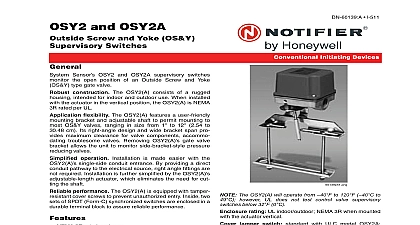
PIBV2 and PIBV2A Indicator Butterfly Valve Switches Sensor PIBV2 and PIBV2A supervisory switches moni the open position of post indicator and butterfly control valves construction The PIBV2 A consists of a rugged intended for indoor and outdoor use When installed the actuator in the vertical position the PIBV2 A is NEMA rated per UL flexibility The PIBV2 A features a flexible that accommodates post indicator butterfly and many types of wall post recessed wall post and pressure valves The PIBV2 A unique bi directional actuator the unit to be installed in either rising or falling flag operation Installation is made easier with the single side conduit entrance By providing a direct pathway to the electrical source right angle fittings are required Installation is further simplified by the PIBV2 A length actuator which eliminates the need for cut the shaft performance The PIBV2 A is equipped with tamper cover screws to prevent unauthorized entry Inside two of SPDT Form C synchronized switches are enclosed in a terminal block to assure reliable performance NEMA 3R rated enclosure Bi directional actuator accommodates rising or falling flags Single side conduit entry does not require right angle fittings Adjustable length actuator eliminates the need for cutting shaft Accommodates up to 12 AWG 3.31 mm wire Two SPDT contacts are enclosed in a durable terminal ratings two sets of SPDT Form C 10.0 A 125 VAC 2.5 A 24 VDC switch dimensions 4.25 H x 3.5 W x 3.25 D 10.8 x 8.9 cm x 8.2 cm stem extension 3 5 32 8.0 cm 1 2 NPT nipple Acceptable PIBV2 A mounting actuator vertical pointing DOWN or actuator hori The following mounting position is NOT accept actuator vertical pointing UP entrances one single side open for 1 2 conduit temperature range 32 to 120 0 to 49 rating UL indoor outdoor NEMA 3R when mounted the actuator vertical I 510 Initiating Devices tamper switch standard with ULC model PIBV2A for UL model P N 546 7000 weight 2 lbs 0.9 kg use Automatic Sprinkler NFPA 13 One or Two Family Dwelling NFPA 13D Residential Occupancies up to 4 stories NFPA 13R National Fire Alarm Code NFPA 72 Specifications shall be model number PIBV2 A Post Indicator Butter Valve supervisory switch as manufactured by System Sen PIBV2 A shall be installed on each valve as designated the drawings and or as specified herein Switches shall be so as not to interfere with the normal operation of the and shall be adjusted to operate within two revolutions the valve control or when the valve flag has moved no more one fifth of the distance from its normal position The shall be contained in a weatherproof die cast housing which shall provide a side entrance for 1 2 and incorporate a 1 2 NPT nipple for attachment to valve body A grounding provision is provided The switch shall include two switches each with a rated capacity 10.0 A 125 250 VAC and 2.5 A 24 VDC The cover contain tamper resistant screws for which a security will be provided with each switch PIBV2 A shall be Laboratories listed for indoor or outdoor use The shall be Factory Mutual CSFM and MEA approved 1 12 10 Page 1 of 2 100 synchronization activates both alarm panel and local Patent No 5,213,205 for added strength simultaneously Line Information Post Indicator Butterfly Valve supervisory switch ULC model Post Indicator Butterfly Valve supervi switch Cover tamper switch kit Listings and Approvals listings and approvals below apply to the PIBV2 or supervisory switches In some cases certain modules not be listed by certain approval agencies or listing may in process Consult factory for latest listing status UL ULC Listed file S739 ULC Listed file CS169 model PIBV2A CSFM approved file 7770 1209 149 7770 1653 118 FM approved MEA approved file 427 91 E 167 93 E BSA approved file 750 76 SA Diagrams nonsilenceable zone of FACP power source with bell switch switch FACP CONNECTION LOCAL BELL CONNECTION WIRE as shown for of connection NOT allow stripped leads to extend switch housing NOT loop wires and System Sensor are registered trademarks of Honeywell Inc by Honeywell International Inc All rights reserved Unauthorized use this document is strictly prohibited document is not intended to be used for installation purposes We try to keep our product information up to date and accurate cannot cover all specific applications or anticipate all requirements specifications are subject to change without notice more information contact Notifier Phone 203 484 7161 FAX 203 484 7118 2 of 2 DN 1785 A1 1 12 10