Notifier SD-551 & SDX-551th Plug-in Intelligent Photoelectronic Sensors

File Preview
Click below to download for free
Click below to download for free
File Data
| Name | notifier-sd-551-sdx-551th-plug-in-intelligent-photoelectronic-sensors-3798104256.pdf |
|---|---|
| Type | |
| Size | 957.47 KB |
| Downloads |
Text Preview
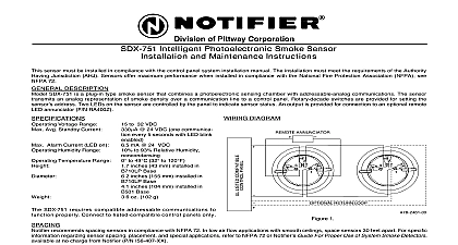
of Pittway Corporation AND MAINTENANCE INSTRUCTIONS MODEL SDX 551 SDX 551TH PLUG IN INTELLIGENT SENSOR WITH COMMUNICATIONS installing sensors please thoroughly read the system wiring and installation manual which provides detailed in on sensor spacing placement zoning and special applications Copies of these manuals are available from DESCRIPTION model SDX 551 SDX 551TH photoelectronic sensor utilizes a state of the art optical sensing chamber This sensor designed to provide open area protection and to be used with compatible UL listed NOTIFIER control panels only for use with panel Model AM2020 Loop Interface Board LIB 200 compatibility ID A maximum number of sen per loop is 99 See 155 531 Revision A for installation and wiring diagrams LEDs on each sensor light to provide a local 360 visibility of the sensor indication The LEDs can be latched ON by command from the panel for an alarm indication The LEDs can also be unlatched to the normal condition by code Remote LED annunciator capability is available as an optional accessory part no RA400Z SDX 551TH adds a thermal heat collector that alarms at a fixed temperature of 135 F Temperature Range Humidity Range Air Velocity Range Current Current GUIDE inches 15.5 cm installed in BX 501 inches 10.4 cm installed in B501 inches 5.8 cm 0.5 inches 1.3 cm for thermal models ounces 272 gm to 120 F 0 to 49 C to 100 F 0 to 38 C to 93 Relative Humidity flanged base flangeless base with RMK400 recessed mounting kit Ft Min 15 m S to 32 Volts DC Peak 24 VDC mA 24 VDC to the installation instructions for the particular plug in base being used 1 for the BX 501 base D550 01 01 2 for B501 base D550 02 00 3 for the RMK400 used with the B501 base D450 07 00 Bases are provided with screw for power ground and remote annunciator connections See Figure 1 All wiring must conform to applicable local codes ordinances and regulations Verify that all sensor bases are installed and that the wiring polarity is correct at each base 12 Clintonville Rd Northford CT 06472 203 484 7161 Remove power from the loop before installing sensors Install sensors Verify that the sensor type matches the type written on the label on the base Set the sensor to a desired address and then write the address on the label on the base Place the sensor into the sensor base Turn the sensor clockwise until it drops into place Continue turning the sensor clockwise until it locks into place Sensor will not detect smoke if dust cover is installed Tamper proof feature sensor bases include a tamper proof feature that when activated prevents removal of the sensor without the use a tool See the installation instruction manual for the sensor base for details in using this feature After all sensors have been installed apply power to the control unit Test all sensors per the TESTING section of this manual ANNUNCIATOR Do not loop wire under terminal 1 or 2 wire run to provide supervision of connections A OPTIONAL WIRING 1 testing notify the proper authorities that the smoke sensor system is undergoing maintenance and therefore the will temporarily be out of service Disable the zone or system undergoing maintenance to prevent unwanted must be tested after installation and periodic maintenance The sensor may be tested in the following ways Test Magnet Model No M02 04 00 Place the magnet against the cover opposite the test module socket to activate the test feature see Figure 2 The LEDs should latch on within 10 seconds indicating alarm and annunciating the panel Test Module Model No MOD400R MOD400R is used with your DMM or voltmeter to check the sensor sensitivity as described in the MOD400R If the sensor sensitivity limits or the MOD400R limits do not appear on the back of the sensor the MOD400R is suitable for field sensitivity testing of that unit MODULE cid 13 2 Views showing position of test magnet Aerosol Generator Gemini 501 per NFPA 72 field test tool is the Gemini Model 510 aerosol generator Set the generator to represent 4 ft to 5 ft obscuration described in the Gemini 501 manual Using the bowl shaped applicator apply aerosol until unit alarms Direct Heat Method Hair dryer of 1000 1500 watts the heat toward the thermal collector holding the heat source about 12 inches away from the detector to avoid to the plastic The detector will reset only after the collector has had sufficient time to cool and the power has been momentarily interrupted This test only verifies proper operation of the sensor and is not used to test sensitivity testing detectors must be reset from the control panel Notify the proper authorities that the system is back on line that fail these tests should be cleaned as described CLEANING and retested If the sensors still fail these they should be returned for repair dust cover is not a substitute for removing sensor during construction or heavy remodeling Cover only helps dust entry SLOT THE SDX 551 SDX 551TH SENSOR Before cleaning notify the proper authorities that smoke sensor system is undergoing mainte and will temporarily be out of service Disable loop or system undergoing maintenance to pre unwanted alarms is recommended that the sensor be removed from its base to facilitate easier cleaning See Figure 3 sensor is cleaned as follows Remove the sensor cover by placing a small bladed in the side slot of the sensor cover twisting it until the cover can be turned counterclockwise for COVER SCREEN cid 13 RS24 W O THERMAL cid 13 W THERMAL 3 Vacuum the screen carefully without removing it If further cleaning is required continue with Step 3 otherwise skip to 6 Remove the screen by pulling it straight out Vacuum the inside Clean the vaned chamber piece by vacuuming or blowing out dust and particles To replace the screen orient it so that the arrow on top aligns with the field test slot on the base of the detector Care push the screen onto the base making sure it fits tightly to the chamber Replace the cover by gently rotating it clockwise until it locks in place of Smoke Detectors smoke detector is designed to activate and initiate emergency action but will do so only when it is used in with an authorized fire alarm system This detector must be installed in accordance with NFPA standard 72 detectors will not work without power AC or DC powered smoke detectors will not work if the power supply cut off detectors will not sense fires which start where smoke does not reach the detectors Smoldering fires do not generate a lot of heat which is needed to drive the smoke up to the ceiling where the smoke detector is located For this reason there may be large delays in detecting a smoldering fire with either an ionization type or a photoelectric type detector Either one of them may alarm only after flaming has initiated which will the heat needed to drive the smoke to the ceiling from fires in chimneys in walls on roofs or on the other side of a closed door s may not reach the smoke and alarm it A detector cannot detect a fire developing on another level of a building quickly or at all For these detectors shall be located on every level and in every bedroom within a building detectors have sensing limitations too Ionization detectors and photoelectric detectors are required to pass tests of the flaming and smoldering type This is to ensure that both can detect a wide range of types of fires detectors offer a broad range of fire sensing capability but they are somewhat better at detecting fast flaming than slow smoldering fires Photoelectric detectors sense smoldering fires better than flaming fires which have if any visible smoke Because fires develop in different ways and are often unpredictable in their growth neither of detector is always best and a given detector may not always provide early warning of a specific type of fire general detectors cannot be expected to provide war