Notifier SDX-751 Intelligent Photoelectronic Smoke Sensors

File Preview
Click below to download for free
Click below to download for free
File Data
| Name | notifier-sdx-751-intelligent-photoelectric-smoke-sensors-3761065418.pdf |
|---|---|
| Type | |
| Size | 408.00 KB |
| Downloads |
Text Preview
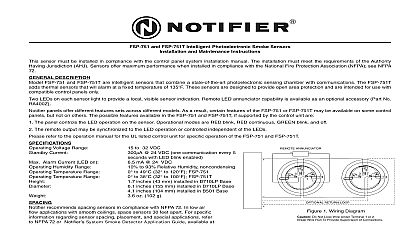
SDX 751 Intelligent Photoelectronic Smoke Sensor and Maintenance Instructions sensor must be installed in compliance with the control panel system installation manual The installation must meet the requirements of the Authority Jurisdiction AHJ Sensors offer maximum performance when installed in compliance with the National Fire Protection Association NFPA see 72 DESCRIPTION SDX 751 is a plug in type smoke sensor that combines a photoelectronic sensing chamber with addressable analog communications The sensor an analog representation of smoke density over a communication line to a control panel Rotary decade switches are provided for setting the address Two LEDs on the sensor are controlled by the panel to indicate sensor status An output is provided for connection to an optional remote annunciator P N RA400Z DIAGRAM ANNUNCIATOR Voltage Range Avg Standby Current Alarm Current LED on Humidity Range Temperature Range to 32 VDC A 24 VDC one communica every 5 seconds with LED blink mA 24 VDC to 93 Relative Humidity to 49 cid 176 C 32 cid 176 to 120 cid 176 F inches 43 mm installed in Base inches 155 mm installed in Base inches 104 mm installed in Base oz 102 g SDX 751 requires compatible addressable communications to properly Connect to listed compatible control panels only RETURN LOOP 1 recommends spacing sensors in compliance with NFPA 72 In low air flow applications with smooth ceilings space sensors 30 feet apart For specific regarding sensor spacing placement and special applications refer to NFPA 72 or Notifier Guide For Proper Use of System Smoke Detectors at no charge from Notifier P N I56 407 XX INSTRUCTIONS wiring must be installed in compliance with the National Electrical Code applicable local codes and any special requirements of the Authority Having Ju Proper wire gauges should be used The installation wires should be color coded to limit wiring mistakes and ease system troubleshooting Im connections will prevent a system from responding properly in the event of a fire power from the communication line before installing sensors wiring must conform to applicable local codes ordinances and regulations Wire the sensor base supplied separately per the wiring diagram Set the desired address on the sensor address switches 5 5 the sensor in to the sensor base Push the sensor into the base while it clockwise to secure it in place After all sensors have been installed apply power to the control unit and the communication line Test the sensor s as described in the TESTING section of this manual 2 Rotary Decade Address Switches covers provide limited protection against airborne dust particles during shipping Dust covers must be removed before the sensors can smoke Remove sensors prior to heavy remodeling or construction testing notify the proper authorities that the system is undergoing maintenance and will temporarily be out of service Disable the system to prevent alarms sensors must be tested after installation and periodically thereafter Testing methods must satisfy the Authority Having Jurisdiction AHJ Sensors offer performance when tested and maintained in compliance with NFPA 72 The sensor can be tested in the following ways Functional Magnet Test P N M02 04 01 sensor can be functionally tested with a test magnet The test magnet electronically simulates smoke in the sensing chamber testing the sensor and connections to the control panel Hold the test magnet in the magnet test area as shown The sensor should alarm the panel LEDs on the sensor are controlled by the panel to indicate sensor status Coded signals transmitted from the panel can cause the LEDs to blink on or latch off Refer to the control panel technical documentation for sensor LED status operation and expected delay to alarm 12 Clintonville Rd Northford CT 06472 203 484 7161 Sensitivity Test Module MOD400R sensitivity test module socket is provided for checking the sensor sensitivity with the MOD400R Test supplied separately Use the test module with a digital or analog voltmeter to check the sensor An acceptable voltage range is stamped on the back of the sensor Test the sensor as de in the test module manual Smoke Entry Aerosol Generator Gemini 501 GEMINI model 501 aerosol generator can be used for smoke entry testing Set the generator to rep 4 ft to 5 ft obscuration as described in the GEMINI 501 manual Using the bowl shaped applica apply aerosol until the panel alarms MODULE sensor that fails any of these tests should be cleaned as described under CLEANING and retested If the fails after cleaning it must be replaced and returned for repair testing is complete restore the system to normal operation and notify the proper authorities that the is back in operation TEST STATUS SENSITIVITY SETTING use of the 0.2 to 0.5 per foot sensitivity setting requires a 90 day test period to ensure that the environment is suitable for this setting The following steps must be followed to meet Notifier and requirements for this high sensitivity application Each detector intended for 0.2 to 0.5 per foot alarm application shall have its initial alarm setting set 0.5 obscuration per foot alarm level The initial prealarm setting for the detector shall be set to the in alarm setting of the system Prealarm shall be set for nonlatching operation Detectors set at 0.2 to 0.5 per foot are intended for use in smoke free environmentally controlled ap such as computer rooms and clean rooms In order to determine if an environment is suitable installation the detectors shall be operated continuously for 90 days with all environmental factors in temperature humidity air flow occupancy etc similar to the intended application for these de An electronic history file or printer shall be used to record all events associated with the detectors testing At the end of 90 days the results of the test shall be inspected by an authorized Notifier representative or end user if trained by an authorized Notifier representative If no alarms or prealarms are recorded for detectors under testing the system may be set to the tested prealarm level in the 0.2 to 0.5 per range is recommended that the detector be removed from its mounting base to facilitate cleaning The detector is as follows removing the detector notify the proper authorities that the smoke detector system is un maintenance and will be temporarily out of service Disable the zone or system undergo maintenance to prevent unwanted alarms Remove the detector cover by prying away the four side tabs with a small bladed screwdriver and then the cover from the base skip to Step 8 Vacuum the screen carefully without removing it If further cleaning is required continue with Step 3 oth Remove the screen assembly by pulling it straight out see Figure 4 Remove the sensing chamber cover by pulling it straight out Clean the vaned chamber piece by vacuuming or blowing out dust and particles Replace the sensing chamber cover aligning the arrow on the top with arrow on the printed circuit board To replace the screen place it over the chamber assembly turning it until it snaps into place Replace the cover using the test module socket and LEDs to align the cover and then gently pushing it it locks into place Reinstall the detector Test the detector as described in TESTING Reconnect disabled circuits Notify the proper authorities that the system is back on line 3 REMOVAL 4 of Smoke Detectors smoke detector is designed to activate and initiate emergency action but will do so only when it is used in conjunction with an authorized fire alarm system This