Notifier SFP-2402(E) 2-Zone Fire Alarm Control Panel

File Preview
Click below to download for free
Click below to download for free
File Data
| Name | notifier-sfp-2402-e-2-zone-fire-alarm-control-panel-7263085194.pdf |
|---|---|
| Type | |
| Size | 650.42 KB |
| Downloads |
Text Preview
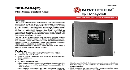
SFP 2402 E Fire Alarm Control Panel Notifier SFP 2402 and SFP 2402E Fire Alarm Control Pan FACPs bring the latest in microprocessor technology to fire controls The SFP 2402 is compatible with the smoke detectors from System Sensor with drift compensa maintenance alert and freeze warning Automatic synchro of audio visual devices with three selections for protocol The Notification Appliance Circuit NAC can silence audible devices while strobes continue to using a single pair of wires SFP 2402 is compatible with conventional input devices as two and four wire smoke detectors pull stations water devices tamper switches and other normally open contact Refer to the Notifier Device Compatibility Document PN for a complete list of compatible devices Unless indicated otherwise the term refers to SFP 2402 and SFP 2402E models Two Style B Class B Initiating Device Circuits IDCs One Style Y Class B NAC 24 VDC Technology features Drift compensation automatically adjusts detector sensitiv and increases resistance to false alarms caused by dust Maintenance Alert LEDs per zone warn of excessive dirt preventing false alarms meets NFPA 72 Detector sensitivity is automatically measured by the which automatically adjusts its sensitivity back to factory settings when it becomes more sensitive due to settling in the chamber Wireless handheld sensitivity meter eliminates the need for magnets and a physical connection to the The reader displays sensitivity in terms of percent foot obscuration and provides text status indication Supervisory LED per zone provides warning if a detector temperature approaching freezing Special test protocol and LED indication allows quick test of detectors without need for a ladder NAC synchronization features Synchronization of standard ANSI audible signals as by NFPA 72 Synchronization of ADA compliant strobes per NFPA 72 Selectable for System Sensor Wheelock and Gentex Selective Silence for manual silence of horns while continue to flash on the same NAC Alarm verification selectable for each zone Disable switches provided per zone NAC programmable for Silence Inhibit Auto Silence Strobe Synchronization Selective Silence horn strobe mute B 90 Fire Alarm Control Panels Temporal or Steady signal Silenceable or Nonsilenceable Silent or audible Walk Test operation mode commanded from front keypad with automatic return to normal after one of inactivity Each zone may be programmed for supervisory or fire each has separate red and yellow LEDs Disable switches provided for each zone Form C Alarm and Trouble relays 3.0 amps total usable current Piezo sounder for alarm trouble supervisory and mainte Control buttons ACK Acknowledge Alarm Silence Reset Walk Test Zone Enable Disable one per zone LED indicators Fire Alarm one per zone Supervisory one per zone Trouble one per zone Maintenance one per zone AC Power NAC Disable Zone Disable NAC Fault System Trouble Power Trouble Walk Test 12 21 11 Page 1 of 2 OUTPUT RESETTABLE POWER TB1 Operating voltage nominal 24 VDC Maximum available current 500 mA appropriate for pow four wire smoke detectors see notes Power limited circuitry 1 Refer to the Notifier Device Compatibility Document 15378 for a complete list of compatible devices Total current for resettable power and one NAC must not 3.0 A for SFP 2402 DIMENSIONS 15.342 38.97 cm high x 14.667 37.28 cm wide x 0.95 cm deep 15.0 38.10 cm high x 14.5 36.83 cm wide x 3.0 cm deep MOUNTING cabinet can be surface mounted The door is removable installation by opening and lifting it off the hinges The mounts using two key slots at the top of the backbox and additional 0.25 diameter holes at the bottom and Approvals UL Listed S635 MEA 297 01 E Vol II CSFM 7165 0028 220 Information Two zone conventional FACP 120 VAC 50 60 Hz A Same as above with 240 VAC 50 Hz 1.15 A oper Battery box required to house two batteries greater 7 AH to a maximum of 18 AH Three input channels model 411 and four input 411UD dual line Digital Alarm Communicator Transmit DACTs Can be used as slave communicators with the Optional trim ring for semi flush mounting 4 zone version of this panel is also available See DN 60377 Alarm Silence Earth Fault on circuit board Battery Fault on circuit board Charger Fault on circuit board Optional dress panel of a compatible smoke detector or any normally open alarm initiating device activates audible and visual signaling illuminates an indicating LED sounds the piezo at the FACP activates the FACP alarm relay and oper an optional module used to notify a remote station or initi an auxiliary control function POWER TB8 SFP 2402 120 VAC 50 60 Hz 2.3 A SFP 2402E 240 VAC 50 Hz 1.15 A Wire Size Minimum 14 AWG 2.0 mm with 600 V insulation SEALED LEAD ACID ONLY J8 Maximum charging circuit normal flat charge 27.6 VCD A Maximum battery charger capacity 18.0 AH battery two AH batteries can be housed in the FACP cabinet Larger require a separate battery box such as the Notifier DEVICE CIRCUIT TB3 Alarm zones 1 2 Power limited circuitry Operation all zones Style B Class B Normal operating voltage nominal 20 VDC Alarm current 15 mA minimum Short circuit current 40 mA maximum Maximum loop resistance 100 ohms End of line resistor 4.7K ohm watt P N 71252 Standby current 4 mA Compatible devices refer to the Notifier Device Compatibility PN 15378 for a complete list of compatible APPLIANCE CIRCUIT TB2 One NAC Power limited circuitry Normal operating voltage nominal 24 VDC Maximum signalling current 2.5 A total with standard trans End of line resistor 4.7K ohm watt P N 71252 Compatible devices refer to the Notifier Device Compatibility PN 15378 for a complete list of compatible RELAYS Trouble Relay TB5 fail safe Alarm Relay TB6 Relay contact ratings 2.0 A 30 VDC resistive is a registered trademark of Honeywell International Inc by Honeywell International Inc All rights reserved Unauthorized use this document is strictly prohibited document is not intended to be used for installation purposes We try to keep our product information up to date and accurate cannot cover all specific applications or anticipate all requirements specifications are subject to change without notice more information contact Notifier Phone 203 484 7161 FAX 203 484 7118 in the U S A 2 of 2 DN 6876 B2 12 21 11