Notifier SFP-5UDC SFP-10UDC Five Zone Fire Alarm Control Panel Ten Zone Fire Alarm Control Panel

File Preview
Click below to download for free
Click below to download for free
File Data
| Name | notifier-sfp-5udc-sfp-10udc-five-zone-fire-alarm-control-panel-ten-zone-fire-alarm-control-panel-7142685390.pdf |
|---|---|
| Type | |
| Size | 739.23 KB |
| Downloads |
Text Preview
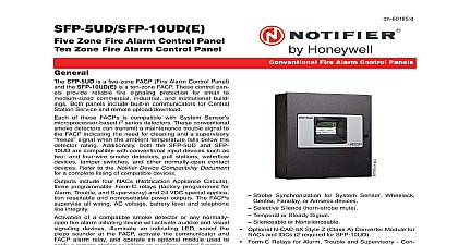
Canadian DN 60437 C Fire Alarm Control Panels Zone Fire Alarm Control Panel Zone Fire Alarm Control Panel SFP 5UDC is a five zone FACP Fire Alarm Control and the SFP 10UDC is a ten zone FACP These control provide reliable fire signaling protection for small to commercial industrial and institutional build Both panels include built in communicators for Central Service and remote upload download of these FACPs is compatible with System Sensor i3 series detectors These conventional detectors can transmit a maintenance trouble signal to FACP indicating the need for cleaning and a supervisory signal when the ambient temperature falls below the rating Additionally both the SFP 5UDC and SFP are compatible with conventional input devices such two and four wire smoke detectors pull stations waterflow tamper switches and other normally open contact Refer to the Notifier Device Compatibility Document a complete listing of compatible devices include four NACs Notification Appliance Circuits programmable Form C relays factory programmed for Trouble and Supervisory and 24 VDC special applica resettable and nonresettable power outputs The FACPs all wiring AC voltage battery level and telephone integrity of a compatible smoke detector or any normally fire alarm initiating device will activate audible and visual devices illuminate an indicating LED sound the sounder at the FACP activate the communicator and alarm relay and operate an optional module used to a remote station or initiate an auxiliary control function Listed to ULC S527 99 S559 01 to UL Standard 864 9th edition Built in DACT Digital Alarm Communicator Transmitter Style B Class B IDC Initiating Device Circuit Style Y Class B NAC Notification Appliance Circuit spe SFP 5UDC five IDCs SFP 10UDC ten IDCs application power SFP 5UDC four NACs SFP 10UDC four NACs Silence Inhibit Auto Silence Strobe Synchronization for System Sensor Wheelock Faraday or Amseco devices Selective Silence horn strobe mute Temporal or Steady Signal Silenceable or Nonsilenceable Optional N CAC 5X Style Z Class A Converter Module for and IDCs 2 required for SFP 10UDC Form C Relays for Alarm Trouble and Supervisory Con Ratings 2.0 A 30 VDC or 0.5 A 30 VAC resistive 7.0 A total system current for SFP 5UDC Notification Appliances may be programmed as DACT 7.0 A total system current for SFP 10UDC Optional Trim Ring TR CE B for semi flush mounting 24 volt operation Low AC voltage sense Alarm Verification PAS Positive Alarm Sequence Automatic battery trickle charger Built in LED Annunciator Module N ANN LED Optional 4XTM module conventional reverse polarity city transmitter AND SOFTWARE Can be programmed at the panel with no special software additional equipment Programmable Make Break Ratio Upload Download local or remote of program and data via INTERFACE Built in DACT Digital Alarm Communicator Transmitter 80 character LCD display with backlighting and Real time clock calendar with automatic daylight savings ANN BUS for connection to annunciators Audible or silent walk test capabilities Piezo sounder for alarm trouble and supervisory 07 26 2010 Page 1 of 4 and Indicators INDICATORS FIRE ALARM red SUPERVISORY yellow TROUBLE yellow AC POWER green ALARM SILENCED yellow BUTTONS ACKNOWLEDGE ALARM SILENCE SYSTEM RESET lamp test DRILL Blocks Power TB1 SFP 5UDC FLPS 7 Power Supply 120 VAC 50 60 HZ SFP 10UDC FLPS 7 Power Supply 120 VAC 50 60 Hz A A Wire size minimum 14 AWG 2.00 mm with 600 V insula Supervised nonpower limited sealed lead acid only J12 Maximum Charging Circuit Normal Flat Charge 27.6 VDC 1.4 A Supervised nonpower limited Maximum Charger Capacity 18 AH battery for SFP 5UDC 26 AH battery for SFP 10UDC Two 18 Ah batteries be housed in the FACP cabinet Larger batteries separate battery box such as the BB 26 or NFS Minimum Battery Size 12 AH Device Circuits TB4 and TB 6 on SFP 10UDC Alarm Zones 1 5 on TB 4 SFP 5UDC and SFP 10UDC Alarm Zones 6 10 on TB6 SFP 10UDC only Supervised and power limited circuitry Operation All zones Style B Class B Normal Operating Voltage Nominal 20 VDC Alarm Current 15 mA minimum Short Circuit Current 40 mA max Maximum Loop Resistance 100 ohms Measurements 2 of 4 Canadian DN 60437 C 07 26 2010 End of Line Resistor 4.7K ohm 1 2 watt P N 71252 UL Standby Current 2 mA to the Notifier Device Compatibility Document for listed devices Appliance Circuits TB5 and TB 7 on SFP only Four NACs Operation Style Y Class B Special Application power Supervised and power limited circuitry Normal Operating Voltage Nominal 24 VDC Maximum Signaling Current 7.0 A for SFP 5UDC 2.5 A per NAC 7.0 A for SFP 10UDC 3.0 A maximum NAC End of Line Resistor 4.7K ohm 1 2 watt Part 71252 Max Wiring Voltage Drop 2 VDC to the Notifier Device Compatibility Document for com listed devices C Relays TB8 Relay 1 factory default programmed as Alarm Relay Relay 2 factory default programmed as fail safe Trouble Relay 3 factory default programmed as Supervisory Relay Application Resettable Power TB9 Jumper selectable by JP31 for resettable or nonresettable Operating voltage 24 VDC nominal Maximum available current 500 mA appropriate for pow four wire smoke detectors Power limited circuit to the Notifier Device Compatibility Document for listed devices Sync Output TB2 Remote power supply synchro output only required for the SFP 5UDC 24 VDC special application power Maximum current is 40 mA Resistor 4.7K ohm Supervised and power lim circuit Line Information Five zone 24 volt Fire Alarm Control Panel black backbox FLPS 7 power supply technical man and a frame post operating instruction sheet Ten zone 24 volt Fire Alarm Control Panel black backbox FLPS 7 power supply technical man and a frame post operating instruction sheet MODULES Optional Class A Converter Module Converts B Class B Initiating Device Circuits to Style D Class A Style Y Class B Notification Appliance Circuits to Style Z A Connects to J2 on the SFP 5UDC and SFP 10UDC circuit board Two Class A Converter Modules are required for the ten panel Transmitter module Provides a supervised output for energy municipal box transmitter and alarm and trouble polarity Includes a disable switch and disable trouble A module jumper option allows the reverse polarity circuit open with a system trouble condition if no alarm conditions Mounts to the main circuit board connectors J4 and J5 ANNUNCIATORS Comes mounted in the dress panel and provides LEDs for each zone Alarm Trouble and Supervisory In applications additional N ANN LED modules can be for remote LED annunciation Black For white order N For red order N ANN LED R Relay module Mounts inside the cabinet Pro ten Form C relays Remote LCD Annunciator for non ULC applica Mimics the information displayed on the FACP LCD For white order N ANN 80 W Serial parallel printer gateway for non ULC Provides a connection for a