VESDA VLF-500 Detector

File Preview
Click below to download for free
Click below to download for free
File Data
| Name | vesda-vlf-500-detector-7495016832.pdf |
|---|---|
| Type | |
| Size | 753.63 KB |
| Downloads |
Text Preview
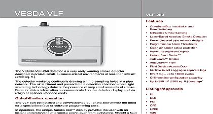
VESDA VLF VESDA VLF 500 detector is a very early warning smoke designed to protect small business critical environments of less 500 m2 5000 sq ft detector works by continually drawing air into sampling holes in a pipe The air is ltered and passed into a detection chamber where light technology detects the presence of very small amounts of smoke status information is communicated on the detector display and via or optional interface cards operation VLF can be installed and commissioned out of the box without the need a special interface or software programming tools operation the unique Smoke DialTM display provides the user with an understanding of a smoke event even from a distance Should a fault the user simply opens the eld service door and activates the Instant Finder feature to determine the speci c fault condition This information then be passed onto their re service company ensuring that service arrive onsite fully prepared Flow Sensing patent pending Ultrasonic Flow Sensing used in the VLF provides a reading of the sampling pipe ow rate The system is immune to air and pressure changes and is unaffected by contamination The is the rst air sampling smoke detector to use ultrasonic ow sensing Out of the Box Installation and Commissioning Ultrasonic Air ow Sensing Laser Based Absolute Smoke Detection Pre engineered pipe network designs Programmable Alarm Thresholds Clean air barrier optics protection Recognition Display Fault Finder AutoLearn Smoke AutoLearn Flow Field Service Access Door Multiple Event Logging in separate logs Event log up to 18000 events Of ine online con guration capability Up to 500 m2 5000 sq ft coverage UL ULC FM CFE LPCB VdS VNIIPO AFNOR ActivFire CE EMC and CPD EN 54 20 Class A 30 holes 0.05 obs m Class B 30 holes 0.15 obs m Class C 30 holes 0.32 obs m cation of any con guration is using ASPIRE2 approvals listings and regulatory compliance vary between product models Refer to www xtralis com for the latest product matrix VLF to 39 32 to 103 to 55 14 to 131 to 60 4 to 140 to 95 RH non condensing x 50 m 150 ft Max 24 holes x 30 m 90 ft per branch Max 12 holes per branch Option or Maximum Pipe length in with Pipe Modelling Design Tool ASPIRE2 DC Nominal 18 30 V DC mA nominal 490 mA in alarm mm x 183 mm x 92 mm 101 16in x 71 5 in x 32 3 in 2 kg 4.4 lbs inverted or horizontal cations Power 24 VDC W x H x D Rating Conditions to Air Network pipe lengths Hole Options Inlet Pipe both metric and American standard pipe sizes 25 mm 1.05 in American Pipe IPS 21 mm in Coverage to 500 m2 5000 sq ft depending on local codes and standards Outputs changeover relays Fire 1 Action Fault Contacts rated 2A 30 VDC max NO NC Contacts Access x 25 mm 11 16 in cable entries 1 rear entry 2 top entry Termination Terminals 0.2 2.5 mm2 30 12 AWG in Terminal Block Connections diagram to right plus an RS232 Programming Port Purpose Input GPI interface offers Reset Disable Standby Alarm set 1 Alarm set 2 External Input functions Threshold Setting Range Action 1 Fire 2 Alarm Delays Alarm Threshold Settings 4 Alarm State Indicators Smoke Level Indicator Reset Disable and Test Controls Smoke and Flow AutoLearn Controls Log to 18000 events time and date stamped in separate non volatile logs for Level Flow Level Detector Status and Faults Smoke Flow Automatically set acceptable alarm thresholds for both smoke and ow levels Minimum 15 minutes maximum 15 days default 14 days During AutoLearn thresholds are NOT changed from pre set values Period years Information VESDA VLF European language set English display labels VESDA VLF European language set International display labels VESDA VLF English Asian language set International display labels VESDA VLF English Russian language set International display labels VESDA VLF English Eastern Euro language set International display labels VESDAnet Interface Card Multifunction Control Card MCC Multifunction Control Card MCC with Monitored Powered Output MPO Filter Cartridge VSP 715 Aspirator for VESDA VLF 500 2.00 obs m 0.008 0.625 obs ft 20.00 obs m 0.008 6.25 obs ft 60 seconds time or GPI based Fault and Disabled Indicators Instant Fault Finder and Europe 44 1442 242 330 D A CH 49 431 23284 1 The Americas 1 781 740 2223 East 962 6 588 5622 Asia 86 21 5240 0077 Australia and New Zealand 61 3 9936 7000 contents of this document are provided on an is basis No representation or warranty either express or implied is made as to the completeness or reliability of the contents of this document The manufacturer reserves the right to change designs or speci cations without obligation without further notice Except as otherwise provided all warranties express or implied including without limitation any implied warranties of and tness for a particular purpose are expressly excluded Xtralis logo The Sooner You Know VESDA ICAM ECO OSID HeiTel ADPRO IntrusionTrace and LoiterTrace are trademarks and registered trademarks of Xtralis and or its subsidiaries in the United States and or other countries Other brand names mentioned herein are for cation purposes only and may be trademarks of their respective holder s Your use of this document does not constitute or create a licence or any right to use the name and or trademark and or label document is subject to copyright owned by Xtralis You agree not to copy communicate to the public adapt distribute transfer sell modify or any contents of this document without the express prior written consent of Xtralis upon local codes and standards outside these parameters will reduce detector life no 10046 19 20298 display provided to the user includes a DialTM and alarm and status indicators the eld service access door is open user has access to the RESET Fire Test AutoLearn Instant Fault Finder functions the Instant Fault Finder function is the Smoke DialTM converts to a indicator with the dial segment numbers to the faults listed below of fault indicators External Device PSU 1 Filter Interface card 2 Aspirator 3 High ow Field wiring AutoLearn Fail 4 Low ow 5 n a Detector failure Block Connections 1 GPI 2 GPI 3 Display TX 4 Display RX 5 Display Common Ground 6 Display Power 7 Display Power 8 Power Return 0 VDC 9 Power In 24 VDC 10 Power Return 0 VDC 11 Power Out 24 VDC 12 NC 13 Common 14 NO 15 NC 16 Common 17 NO 18 NC 19 Common 20 NO power unit next detector more than 1 detector Power Supply Unit relay relay 1 relay Compliance refer to the Product Guide for details compliant design installation and Product UL listed for use from 0 to 38 32 to 104