Potter CS-24 Series Wall Mount Colored Lens Strobe

File Preview
Click below to download for free
Click below to download for free
File Data
| Name | potter-cs-24-series-wall-mount-colored-lens-strobe-2684371950.pdf |
|---|---|
| Type | |
| Size | 1.68 MB |
| Downloads |
Text Preview
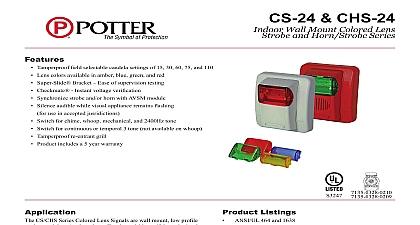
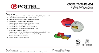
Features Tamperproof field selectable candela settings of 15 30 60 75 and 110 Lens colors available in amber blue green and red Super Slide Bracket Ease of supervision testing Checkmate Instant voltage verification Synchronize strobe and or horn with AVSM module Silence audible while visual appliance remains flashing for use in accepted jusridictions Switch for chime whoop mechanical and 2400Hz tone Switch for continuous or temporal 3 tone not available on whoop Tamperproof re entrant grill Product includes a 5 year warranty CS CHS Series Colored Lens Signals are wall mount low profile and horn strobes that offer dependable audible and visual for warning and emergency notification Applications include communication severe weather emergency response and more CS CHS Series Colored Lens Signals are 24VDC units available lens colors of amber blue green and red The Series offers field selectable options of 15 30 60 75 and 110 candela have a minimal operating current and a minimum flash rate of regardless of input voltage The strobes can be synced using a sync protocol or the AVSM Sync Module Colored Lens Series is shipped with a die cast universal 4 bracket which incorporates the popular Super Slide that allows the installer to easily pre wire the system and test supervision The product also features a locking mechanism that the signal to the bracket without showing any screws The Lens Series also features the Checkmate Instant Voltage Feature which allows the installer to check the voltage current draw and match against the blue print Listings ANSI UL 464 and 1638 7135 0328 0210 CHS Series 7135 0328 0209 CS Series Specifications Voltage Limitations Connections Weight 24VDC 16 33VDC 120 0 49 Only H x 4.5 W x 2.5 D accept 18 12 AWG gang double gang or 4 backbox mount with AVBB lbs PAGE 1 OF 4 CHS 24Indoor Wall Mount Colored Lens Strobe and Horn Strobe Series8830055 REV B 10 14Potter Electric Signal Company LLC St Louis MO Tech Support 866 956 1211 Customer Service 866 572 3005 www pottersignal comfirealarmresources com Number Color dBA at 10 per ANSI UL 464 Anechoic Room dBA at 10 Series Colored Lens Strobe Selectable Candela Number Series Colored Lens Strobe Selectable Candela Color Max Strobe Current Ratings 24VDC Regulated Gree and Lens Lens unfiltered FWR ratings see installation manual Bezels Number CS CHS Series devices are plain no wording bezels can be ordered separately Decibel and Current Ratings at 10 UL 464 at 10 UL 464 24VDC Operating at High mA Setting 3 2400Hz 3 Mechanical 3 Chime 2400Hz Mechanical Chime the horn in this mode at this voltage will result in not meeting minimum ANSI UL 464 reverberant sound level required for public fire protection service These settings are acceptable only for mode fire alarm use Use the high dBA setting for public mode not applicable when using the chime tone The chime tone always private mode PAGE 2 OF 4 8830055 REV B 10 14Potter Electric Signal Company LLC St Louis MO Tech Support 866 956 1211 Customer Service 866 572 3005 www pottersignal comCS 24 CHS 24Indoor Wall Mount Colored Lens Strobe and Horn Strobe Seriesfirealarmresources com Switch Locations Temporal 3 Continuous Temporal 3 Continuous Temporal 3 Continuous Position Positions 1 and 2 in the OFF position to select horn and strobe power inputs Position 6 ON HIGH dBA Position 6 OFF LOW dBA Slide Mounting Bracket the installer to pre wire the system test for system remove the signal head until occupancy switch signals without changing mounting brackets and has edge connector for snap in place installation selection slider switch center and slide switch desire brightness level off pin and insert hole at the bottom of selector to lock candela Signal must be from bracket and pushed forward from out of the hole to candela Instant Voltage is often necessary to confirm the voltage along the line of devices The access are provided in the back of the block to allow the voltage to measured directly without removing device Typically this would be done the end of the line to confirm design Most measurements will be taken the S and S locations although is provided to other locations Care should be taken to not the test probes remove bezel grip both sides of bezel pull in a download and outward PAGE 3 OF 4 CHS 24Indoor Wall Mount Colored Lens Strobe and Horn Strobe Series8830055 REV B 10 14Potter Electric Signal Company LLC St Louis MO Tech Support 866 956 1211 Customer Service 866 572 3005 www pottersignal comfirealarmresources com Diagrams All strobes are designed to flash as specified with continuous applied voltage Strobes should not be used on coded or pulsing signaling circuits use of the AVSM control module or Gentex synchronization protocol is permitted to synchronize the strobe horn and or mute the horn SYNCHRONIZATION WIRING INFORMATION REFERENCE AVSM CONTROL MODULE DATA SHEET 8830050 AND OR CONTROL MODULE MANUAL FOR SYNCHRONIZATION MODULE WIRING DIAGRAMS AVSM CONTROL MODULE SHEET AND MANUAL CAN BE OBTAINED AT http pottersignal com OR CALL POTTER ELECTRIC AT 1 800 325 3936 and Engineering Specifications audible and or visible signal shall be Potter Colored Lens Series or approved equal and shall be listed by Underwriters Laboratories Inc per ANSI UL and ANSI UL 464 and shall have compliance with the polar dispersion requirements of ANSI UL 1971 The notification appliance shall also be listed the California State Fire Marshal CSFM notification appliance combination audible visible shall produce a peak sound output of 100dBA or greater as measured in an anechoic chamber The appliance shall also have the capability to silence the audible signal while leaving the visible signal energized with the use of a single pair of power Additionally the user shall be able to select either continuous or temporal tone output with the temporal signal having the ability to be synchronized shall be capable of being installed so that any unauthorized attempt to change the candela setting will result in a trouble signal at the fire alarm control audible visible and visible signaling appliance shall also maintain a minimum flash rate of 1Hz or up to 2 Hz regardless of power input voltage The shall have an operating current of 74mA or less at 24 VDC for the 15Cd strobe circuit appliance shall be polarized to allow for electrical supervision of the system wiring The unit s