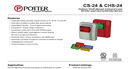
Potter CSH24W Series Wall Mount Colored Horn Strobe

File Preview
Click below to download for free
Click below to download for free
File Data
| Name | potter-csh24w-series-wall-mount-colored-horn-strobe-4069328715.pdf |
|---|---|
| Type | |
| Size | 1.05 MB |
| Downloads |
Text Preview
A Brand CSH24W LIGHT SERIES Limitless applications Weather warning mass noti cation leaks etc Selectable candela output NFPA ANSI compliant UL listed for wall mounting Polarized strobes with wide operating voltage range using ltered DC or un ltered FWR input voltage Horn eld selectable tones Universal mounting plate for 4 single gang back box and more Synchronization using Sync Module SMD10 3A Available in red or white housing Available strobe colors amber blue green red Hz interrupted or electro mechanical or Non temporal or low dBA output Amseco Colored Strobe utilizes a patented design that produces a true color output The CSH24W offer a slim line look with a stylish round The CSH24W colored strobe horns are UL listed for indoor applications The terminal strips accept a wide cable offering and provide a connection of one or multiple devices The strobe horn combinations are selectable with either a continuous or ANSI Temporal 3 output strobes are used in various applications such as Mass Noti cation Severe Weather Warning Machine Operation Industrial Detection Access Control and many many more These devices are UL listed for general signaling UL 1638 and comply with the requirements signaling of the hearing impaired UL 1971 The bodies of the strobes are available in red or white The strobes are designed for 24 VDC will operate anywhere between 16 and 33 VDC Information Color Voltage Type Output Rate Range Number Potter before ordering 24V FWR Mount times 120 49 Speci cations Amseco CSH24W colored strobe horn shall be provided for visual and audible noti cation The device shall have a universal mounting and connect to a single gang double gang four inch square or octagon box The devices shall be UL listed for General Signaling and shall with light output requirements of UL 1971 for spacing The colored strobes shall have a minimum light output of 15 cd The re ective shall be the same color as the lens to produce a true color of amber red blue or green The strobe shall operate between 16 and 33 VDC or full wave recti ed The strobe shall ash a minimum of once a second continuously at 16 VDC inches mm 127 85.7 127 View View View Electric Signal Company 2081 Craig Road St Louis MO 63146 4161 Phone 800 325 3936 Canada 888 882 1833 www pottersignal com IN USA 8850036 REV B 9 07 1 OF 3 CSH24W LIGHT SERIES Only RMS operating mA DC 57 87 FWR 95 135 ULC Current 24V mA either Low or High replace cap on front of unit High Proof strobe horn must be used only on circuits with continuously voltage DO NOT use strobe on coded or interrupted in which the applied voltage is interrupted ON and OFF as strobe may fail to ash The applied voltage must be within its input voltage range Fuse ratings on signaling circuits must peak currents from all devices connected to those circuits Brand cations Output Output on Axis cd 45 45 Diagram 1 2 Operates Independently Signal to Fig 1 Next or Next or Signal Next or 3 Diagram for Audible Strobe supervised Class B Circuit with Audible Silence Feature CSH24W to Fig 2 Signal Signal MODULE H Next or 4 Diagram for Audible Strobe supervised Class B Circuit without Audible Silence Feature MODULE H to Fig 2 Next or setting jumper wire 8850036 REV B 9 07 IN USA 2 OF 3 LIGHT SERIES Options Plate Gang Box Square Back Box Gang Box Brand Current Draw Table Pattern Tone Volume RMS Current PC2 PC1 Regulated DC FWR Sound dBA at per UL464 24V Hz HIGH Hz 1 Electro Hz Electro Hz Electro Hz Electro Hz Electro Hz 1 HIGH 0 0 1 1 0 0 1 1 0 0 99 145 80 120 99 145 80 99 80 99 80 130 111 130 111 130 111 130 111 120 145 120 145 120 185 160 185 160 185 160 185 160 Output dB dB Only Only IN USA 8850036 REV B 3 OF 3