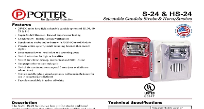
Potter HS-24 Series Selectable Candela Wall Mount Horn Strobe

File Preview
Click below to download for free
Click below to download for free
File Data
| Name | potter-hs-24-series-selectable-candela-wall-mount-horn-strobe-8405612973.pdf |
|---|---|
| Type | |
| Size | 1.39 MB |
| Downloads |
Text Preview
Features 24VDC Super Slide Checkmate Synchronize Prewire Documented Switch Switch Tamperproof Switch Silence Faceplate Specifications 12 AWG PAGE 1 OF 4 Electric Signal Company LLC St Louis MO Phone 800 325 3936 www pottersignal com8830054 REV C 6 17S 24 HS 24 Selectable Candela Strobe Horn StrobesS3247firealarmresources com Selection selection switch Depress and slide switch to brightness level off pin and insert into at the bottom of the to lock candela Signal must be from bracket and pushed forward from out of hole to candela Locations Instant Voltage Verification access holes are provided in the back of the terminal to allow the voltage to be measured directly without the device Typically this would be done at the of the line to confirm design criteria Most measure will be taken using the S and S locations although is provided to other locations NOTE Care should taken to not short the test probes Slide Mounting Bracket the installer to pre wire the system test for system remove the signal head until occupancy switch signals without changing mounting brackets and has edge connector for snap in place installation remove bezel both sides of and pull in downward and motion PAGE 2 OF 4 Electric Signal Company LLC St Louis MO Phone 800 325 3936 www pottersignal comS 24 HS 24 Selectable Candela Strobe Horn Strobes8830054 REV C 6 17firealarmresources com 24 VDC Selectable Candela Low Evacuation Strobe VDC VDC 24 VDC Selectable Candela Profile Evacuation Strobe VDC VDC HS 24 Strobe Current Ratings VDC 16 33 Volts cd cd cd cd cd VDC mA mA mA mA mA Max mA mA mA mA mA HS 24 Horn Ratings Designations Electric Signal Company LLC St Louis MO Phone 800 325 3936 www pottersignal comS 24 HS 24 Selectable Candela Strobe Horn Strobes8830054 REV C 6 17firealarmresources com HS 24 Series Wiring Diagram Engineering Specifications