Potter InstallationManual EH-HS-S-CHS-CS-Series

File Preview
Click below to download for free
Click below to download for free
File Data
| Name | potter-installationmanual-eh-hs-s-chs-cs-series-1290358476.pdf |
|---|---|
| Type | |
| Size | 1.49 MB |
| Downloads |
Text Preview
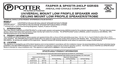
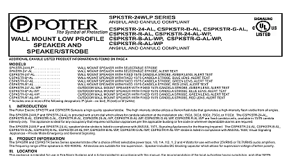
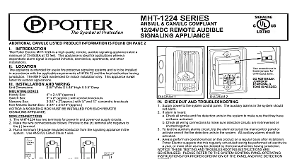
HS24 177 S24 177 EH 24 HS 24 S 24 SERIES CAN ULC COMPLIANT HSLP 24 WP S 24 WP SLP 24 WP SERIES CS 24WA CHS 24B CS 24WB CHS 24G CHS 24R CS 24WR SERIES CHSLP 24A WP CS 24WA WP CSLP 24WA WP CHSLP 24B WP CS 24WB WP CSLP 24WB WP CHSLP 24G WP CS 24WG WP CSLP 24WG WP CHSLP 24R WP CS 24WR WP CSLP 24WR WP SERIES CAN ULC COMPLIANT AND OR AUDIBLE APPLIANCES CAN ULC LISTED PRODUCT INFORMATION IS FOUND ON PAGES 5 AND 6 INTRODUCTION Potter Electric models HS24 177 S24 177 EH 24 HS 24 S 24 HS 24 WP HSLP 24 WP S 24 WP SLP 24 WP CHS 24A CS 24WA CHS 24B CS 24WB CHS 24G CS 24WG CS 24WR CHS 24A WP CHSLP 24A WP CS 24WA WP CSLP 24WA WP CHS 24B WP CHSLP 24B WP CS 24WB WP CSLP 24WB WP CHS 24G WP CHSLP 24G WP CSLP 24WG WP CHS 24R WP CHSLP 24R WP CS 24WR WP CSLP 24WR WP are high quality audible and or visible signaling appliances The high intensity strobe utilizes Xenon flash tube that generates a high intensity flash visible from all angles This appliance is intended to provide a visible audible or audible visible depending on the model notification for the purpose of life safety and property protection The HS 24 S 24 CHS 24A CS 24WA CHS 24B CS 24WB CHS 24G CS 24WG CHS 24R CS 24WR are provided with a slider which allows for candela selection at the installation site the candela intensities which can be selected are 15Cd 30Cd 60Cd 75Cd or 110Cd The HS24 177 and S24 177 are fixed units the candela intensity which can be ordered is 177Cd The HS 24 WP HSLP 24 WP S 24 WP SLP 24 WP CHS 24A WP CHSLP 24A WP CS 24WA WP CSLP 24WA WP CHSLP 24B WP CS 24WB WP CSLP 24WB WP CHS 24G WP CHSLP 24G WP CS 24WG WP CSLP 24WG WP CHS 24R WP CHSLP 24R WP CS 24WR WP are fixed candela units available in a 75 candela intensity only This appliance is ideal for any occupancy that requires notification appliances per the applicable building or fire or wherever dependable alarms are required HS24 177 S24 177 HS 24 S 24 strobe is listed in compliance with ANSI UL 1971 Signaling Appliances for the Hearing Impaired The HS 24 WP HSLP 24 WP S 24 WP SLP 24 WP CS 24WA CHS 24B CS 24WB CHS 24G CS 24WG CHS 24R CS 24WR CHS 24A WP CHSLP 24A WP CS 24WA WP CSLP 24WA WP CHS 24B WP CHSLP 24B WP CSLP 24WB WP CHS 24G WP CHSLP 24G WP CS 24WG WP CSLP 24WG WP CHS 24R WP CHSLP 24R WP CS 24WR WP CSLP 24WR WP strobe is listed in with ANSI UL 1638 Visual Signaling Appliances Private Mode Emergency and General Signaling Additionally colored lens models CHS 24A CS 24WA CHS 24B CS 24WB CS 24WG CHS 24R CS 24WR comply with the polar dispersion requirements of ANSI UL 1971 LOCATION appliance is intended for use in Fire Alarm Systems and is to be installed in accordance with this manual the recommendation of the local authorities having jurisdiction and other NFPA that provide standards on notification appliances for protective signaling systems The HS24 177 S24 177 EH 24 HS 24 S 24 CHS 24A CS 24WA CHS 24B CS 24WB CS 24WG CHS 24R CS 24WR are intended for indoor installations only this appliance is not listed for outdoor or drip proof applications The HS 24 WP HSLP 24 WP S 24 WP CHS 24A WP CHSLP 24A WP CS 24WA WP CSLP 24WA WP CHS 24B WP CHSLP 24B WP CS 24WB WP CSLP 24WB WP CHS 24G WP CHSLP 24G WP CS 24WG WP CHS 24R WP CHSLP 24R WP CS 24WR WP CSLP 24WR WP are intended for indoor or outdoor installations this appliance is rated for outdoor or drip proof applications used in conjunction with the WPBB or WPLPBB Enclosure mounted strobe and horn strobe appliances shall have their entire lens at heights above the finished floor of not less than 80 in 2m and not greater than 96 in 2.4m Spacing shall be accordance with Table A If a room configuration is not square the room size that will entirely encompass the room or subdivide the room into multiple squares shall be used Wall mounted only appliances shall have their tops above the finished floors at heights of not less than 90 in 2.30m and below the finished ceilings at heights of not less than 6 in 152mm Different heights shall be permitted by the AHJ provided the sound pressure level requirements of NFPA 72 are met MOUNTING ROUGH IN BOX AND RUN WIRING unit is designed for mounting to most single gang boxes 4 square outlet boxes 2 gang masonry boxes or non metallic 2 gang switch boxes Conduit entrance to boxes should be to insure sufficient wiring clearance Run a minimum 18 gauge insulated 2 or more conductor cable Mount a box for each remote signaling appliance Screw bracket onto box Insert signal into bracket and slide to the right firmly into the terminal block Place housing over mounted assembly and screw together with single screw at the bottom of the signal Cover screw with plastic tab WIRING SHOULD BE CONNECTED TO MOUNTING BRACKET PRIOR TO MOUNTING SIGNAL INCOMING POSITIVE POWER LEAD MUST BE BROKEN AND EACH LEAD IS BE INSERTED INTO EACH OF THE TOP TWO TERMINALS IF TWO POWER RUNS ARE MADE TO THE SIGNAL ONE FOR THE STROBE AND ONE FOR THE HORN ONLY ONE OF RUNS MUST HAVE ITS POSITIVE LEAD BROKEN AND PLACED UNDER THE TWO SEPARATE TOP TERMINALS A BARRIER IS PROVIDED TO PREVENT BOTH LEADS FROM PLACED UNDER THE SAME TERMINAL S24 177 HS 24 AND S 24 PRODUCT INFORMATION A Light Room Required Light Output Effective Intensity Cd Lights per Room Light per Wall Spacing for Wall Mounted Visible Appliances per NFPA 72 2013 Edition Room Size x 20 x 28 x 30 x 40 x 45 x 50 x 54 x 55 x 60 x 63 x 68 x 70 x 80 x 90 x 100 x 110 x 120 x 130 x 6.10 x 8.53 x 9.14 x 12.2 x 13.7 x 15.2 x 16.5 x 16.8 x 18.3 x 19.2 x 20.7 x 21.3 x 24.4 x 27.4 x 30.5 x 33.5 x 36.6 x 39.6 Not allowable Intensity Requirements for Sleeping Areas Notification Appliance from Ceiling to Top of Lens than or equal to 24 than 24 light must be within 16 feet the pillow when used a sleeping area 1 light cannot be seen when objects such as doors furniture or walls block strobe light THE VISUAL SIGNAL MUST BE IN THE DIRECT VIEWING AREA OF THE OCCUPANT IN ORDER TO BE SEEN VISUAL SIGNALS FOR THE HEARING IMPAIRED ARE ONLY ONE METHOD OF ALERTING THE HEARING IMPAIRED VISUAL SIGNALS MAY NOT BE THE PREFERRED METHOD THE STROBE LIGHT MUST BE SEEN BY THE SLEEPING PERSON IF THE PERSON HAS HEAD TURNED OR OTHERWISE UNABLE TO BE ALERTED BY VISUAL THE STROBE NOTIFYING ALL HEARING IMPAIRED INDIVIDUALS NOT BE EFFECTIVE CLEAR Lens Indoor Strobe Current Ratings and Series Candela and HS 24 Available 24VDC Operating 24VFWR Operating mA Operating mA DC VOLTAGE RANGE LIMITS 16 33V FWR RANGE LIMITS 16 33V THIS PRODUCT WAS TESTED TO THE STATED VOLTAGE RANGE S DO APPLY 80 AND 110 OF THIS RANGE FOR OPERATION 24VDC nominal operating current data not available HSLP 24 WP S 24 WP SLP 24 WP CHS 24A WP CHSLP 24A WP CS 24WA WP CSLP 24WA WP CHS 24B WP CS 24WB WP CSLP 24WB WP CHS 24G WP CHSLP 24G WP CS 24WG WP CSLP 24WG WP CHSLP 24R WP CS 24WR WP AND CSLP 24WR WP PRODUCT INFORMATION BLUE GREEN RED Lens Outdoor Current Ratings with CHS 24B WP CHSLP 24B WP CSLP 24WB WP CHS 24G WP CS 24WG WP CSLP 24WG WP CHSLP 24R WP CS 24WR WP CSLP 24WR WP Products 24VDC Operating mA 24VFWR Operating mA CLEAR AMBER Lens Outdoor Current Ratings with HS 24 WP HSLP 24 WP S 24 WP CHS 24A WP CHSLP 24A WP and CSLP 24WA WP Products 24VDC Operating mA 24VFWR Operating mA DC VOLTAGE RANGE LIMITS 16 33V FWR VOLTAGE RANGE LIMITS 16 33V THIS PRODUCT WAS ONLY TESTED TO STATED VOLTAGE RANGE S DO NOT APPLY 80 AND 110 OF THIS RANGE FOR SYSTEM OPERATION Lens Indoor Strobe Current Ratings with CHS 24A and CS 24WA Products GREEN RED Lens Indoor Current Ratings with CHS 24B CS 24WB CHS 24G CHS 24R and CS 24WR Products 24VDC Operating mA 24VFWR Operating mA 24VDC Operating mA 24VFWR Operating mA