Potter LWCO Low Water Cutoff LFSeriesTACO

File Preview
Click below to download for free
Click below to download for free
File Data
| Name | potter-lwco-low-water-cutoff-lfseriestaco-6204817539.pdf |
|---|---|
| Type | |
| Size | 1005.43 KB |
| Downloads |
Text Preview
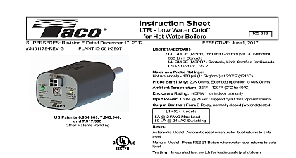
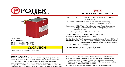
Instruction Sheet Compensating Low Water Cutoff with Button and DualVision REVISION G DATED December 22 2008 H ID 001 3908 April 27 2009 UL GUIDE MBPR for Limit Controls per UL Standard 353 Limit UL GUIDE MCUR2 for Electrode Assemblies Component CUL per CSA Standard C22.2 No 205 M1983 FM Approved For applications with a supervised burner system Fully compliant with CSD 1 requirements Fitting Thread 3 4 NPT Control Unit NEMA Type 1 For indoor use only Formed sheet with powder coat plated nish Five openings for 1 2 conduit ttings Hot Water 250 psi 17.6kg cm2 Pressures Steam 250 psi 17.6kg cm2 Probe Temperature 250 F 121 C Ambient Temperature 150 F 66 C Delay on Make DOM and Delay on Break DOB automatically provided based upon boiler conditions Compensating The DualVision technology provides protection against false water level detection due to being in foam Automatic detection of foaming conditions shutdown of boiler when water level becomes unsafe intermittent shutdown of the boiler Sensitivity Extended operation to 20K Ohms Supply Voltage Service range 20K to 40K Ohms Voltage Consumption 24VAC to be supplied by EXTERNAL Class 2 power VAC VAC VA VA also allows the LF series to identify reduced probe signal due to fouling and turns on an LED light when the probe should inspected and cleaned The LFA models automatically reset when levels return to safe levels The LFA control may be used with an or with an automatic water feeder EWF to keep the boiler lled the proper level The LFM models are manual reset models Once low water level has returned to proper levels the reset switch on the must be pressed to restore the system to normal operation a low water condition the LED will illuminate RED In conditions it will illuminate GREEN If the LFA detects foaming LED will blink AMBER If the LFA detects a low signal from the probe the LED will illuminate AMBER signal that probe cleaning may be required See Fig 3 for LED details LF series will not lock out upon power loss provided water remains the probe They fully comply with CSD 1 requirements Patents 6,904,800 and 7,317,993 Patents Pending Rating Ratings Switch Rating Load Rotor or 60 Hz A A A A VA VA VAC VAC VAC Foam Compensating Low Water Cutoffs LF series are microprocessor based low water cutoffs for detecting the of a conductive uid in a vessel or tank The LF series is designed for use in low pressure steam and hot water boilers cutoff the burner in low water level conditions They may be used as the primary or secondary cutoff on low pressure steam boilers as the primary low water cutoff on hot water boilers Additionally can protect pumps from running dry in condensate receiver tank or activate alarm systems or automatic water feeders See boiler manufacturers speci cations for recommended minimum water levels LF series uses its DualVision technology to identify when its is in foam and the boiler water is at an unsafe level The LF cannot be fooled by the presence of conductive foam on its and it does not require periodic shutdowns of the boiler to actual water levels in foaming boilers The DualVision Installation must be performed by quali ed personnel and in accordance with all national and local codes and ordinances Read all instructions carefully and understand them before starting installation Save instructions for future use Instruct user how to test and operate this cutoff device as described in these instructions Shock Hazard Disconnect power source before servicing Serious injury or death could result Risk of explosion Not for use in hazardous locations Serious injury or death could result The LWCO device must be installed in series ahead of other limit and operating controls installed on the boiler When installations are complete check for correct operation of ALL limit and operating controls Wire insulation must be rated at 167 F 75 C or greater over copper conductors only Use of other wire or insulation types could result in re causing property damage serious injury and death Foam in boiler or piping can cause improper operation If the boiler is foaming shutdown the boiler and clean it per the manufacturers recommendations to eliminate foaming Failure to do so could result in damage to the equipment and property or could cause an explosion resulting in serious injury or death Use only the probe that is supplied with this control or replacement probe P3S 1 Failure to do so could result in improper operation damage to the equipment and property or could cause an explosion resulting in serious injury or death Hot or pressurized boiler systems can discharge steam and hot water Cool boiler system to 80 F 27 C and to 0 psi 0 bar before servicing Failure to do so could result in serious burns Do not tighten by grasping the device enclosure Use wrenching ats on the probe bushing only Failure to install properly could damage the device and cause improper operation resulting in damage to equipment and property Do not use manual reset low water cutoffs with automatic water feeders Flooding equipment damage and property damage can result Only use automatic water feeders with automatic reset low water cutoffs SPACING REQUIREMENTS 1 UNIT MOUNTED ON PROBE 2 not mount device with probe angled upward or deposits can in the probe Mount only with probe facing horizontally vertically downward and maintain 1 4 minimum clearance from and pipe wall Failure to install probe as directed can improper operation and damage to equipment and property SCREW 3 CONNECTION 1163 9A INSTALLED JUMPER IF LWCO POWER IS DIFFERENT BURNER POWER Fig 6 Water Indicators LED LED Detected Safe Water Level Detected and Low Water Probe Service Soon Probe Unsafe to Operate Failure Detected Red Off Amber Amber PROBE BLOCK WIRING 24 VAC ONLY SWITCH SERVICE LED STATUS LED SWITCH 1163 7B UNIT OUTLINE DWG 4 WIRING DIAGRAM USING CIRCUIT POWER SOURCE 5 WIRING DIAGRAM USING SOURCE OTHER THAN BLOCK CONNECTIONS PLATE TERMINAL CIRCUIT 7 6 insulation must be rated at 167 F C or greater Use at least 18 AWG conductors or as required by Use of other wire or insulation could result in re causing property or serious injury Remote probe available remote probe models only NOTES FOR ALL PROBE INSTALLATIONS pipe thread sealant only for sealing probe threads Do not te on tape Use of te on tape can insulate probe electrically can cause improper device operation and damage to or property Be sure the probe is installed above the minimum safe water as determined from the boiler manufacturer literature Be sure the probe extends into the boiler cavity so that contact the water is made Be sure the exposed portion of the stainless steel probe is a of 1 4 from any grounding surface inside the boiler prevent the probe from shorting see Fig 1 only the probe that is supplied with this control or probe P3S 1 Failure to do so could result in operation damage to the equipment and property or cause an explosion resulting in serious injury or death Unit Mounting onto Probe See Fig 2 Tighten the probe into the tapped location of the boiler with a