Potter MOM-4 Monitored Output Module
File Preview
Click below to download for free
Click below to download for free
File Data
| Name | potter-mom-4-monitored-output-module-4392068157.pdf |
|---|---|
| Type | |
| Size | 1.60 MB |
| Downloads |
Text Preview
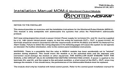
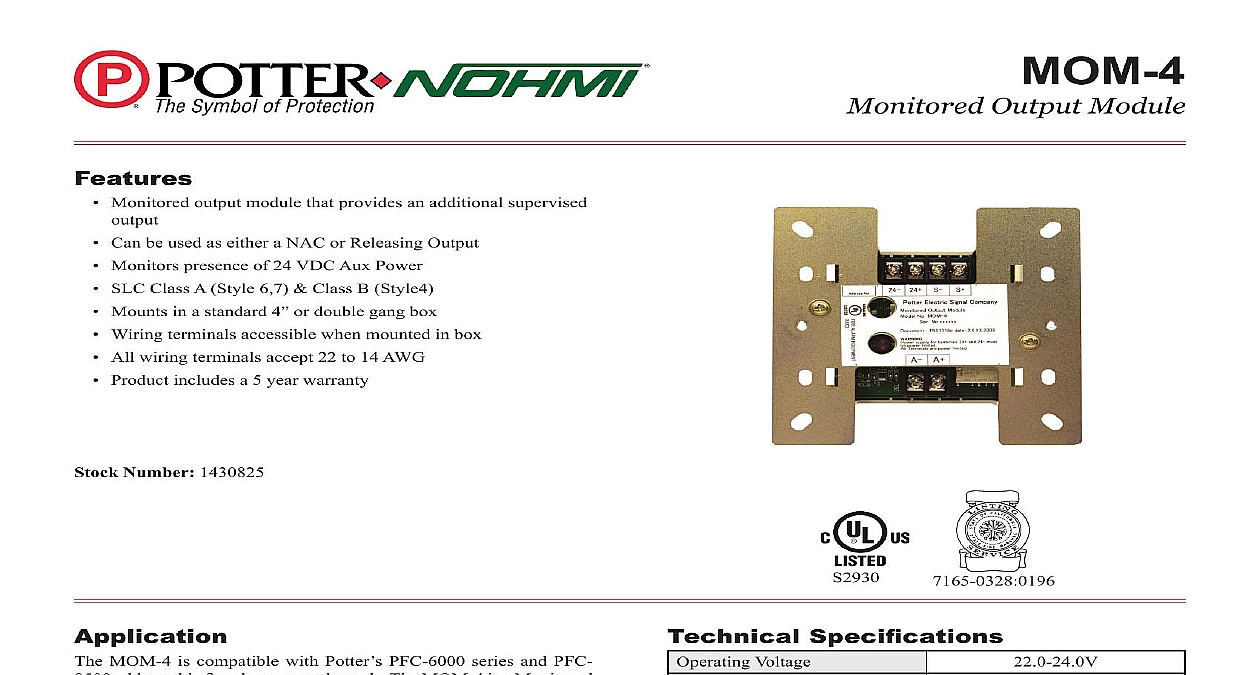
Features Monitored output module that provides an additional supervised Can be used as either a NAC or Releasing Output Monitors presence of 24 VDC Aux Power SLC Class A Style 6,7 Class B Style4 Mounts in a standard 4 or double gang box Wiring terminals accessible when mounted in box All wiring terminals accept 22 to 14 AWG Product includes a 5 year warranty Number 1430825 MOM 4 is compatible with Potter PFC 6000 series and PFC addressable re alarm control panels The MOM 4 is a Monitored Module that wires to the SLC loop to provide an additional cation circuit When used with a Potter addressable relasing the MOM 4 can provide an additional releasing circuit MOM 4 module uses one 1 address on an SLC Loop The provides a programmable source of power to supervise and a Noti cation Appliance or a Releasing Circuit The module and supervises a 24 VDC auxiliary power connection The includes one red LED to indicate the modules status In condition the LED ashes when the device is being polled the control panel in case of an open circuit the LED will turn off Output Module Specifi cations Voltage SLC Standby Current SLC Alarm Current Power Required Ratings Wiring Cpacitance of Circuit Wiring Resistor VDC VDC 2A Resistor Diode Tempurature Range Humidity Range no of Module Per Loop Options Weight 3005012 Releasing Not Included to 120 0 to 49 to 93 non condensing units 106mm L 4.17 1.14 29mm 4 Square or Gang Box lbs Electric Signal Company LLC St Louis MO Tech Support 866 956 0988 Customer Service 866 572 3005 www pottersignal com REV D 7 14 PAGE 1 OF 2 the Address addressable SLC device must be assigned an address prior to installation The address is set using either the hand held device programmer or the feature on the PFC 6000 PFC 8500 series control panels connecting a device to the SLC loop take the following precautions to prevent potential damage to the panel or device verify the following Power to the device is removed Field wiring is correctly installed Field wiring has no open or short circuits Using Compatible Electrical Box Wiring Diagram for an Output Connected to a Notification Appliance Circuit FACP or Previous Module Loop Next Module FACP or Previous Module Next Module The resistence of external wiring shall be less than 100 capacitance of external wiring shall be less than 1 micro farads DC Rating 2.0A Appliance Output Module No MOM 4 1 2W EOLR 593 18 If strobe synchronization is required a synchronization module must be installed on the output circuit Wiring Diagram for a Releasing Application is possible that the internal relay in the MOM 4 may be shipped in the non normal activated state To ensure that the internal relay is set to the state connect the module to the SLC loop and reset the control panel before terminating the wiring to the modules output terminals A A PAGE 2 OF 2 8830003 REV D 7 14Potter Electric Signal Company LLC St Louis MO Tech Support 866 956 0988 Customer Service 866 572 3005 www pottersignal comMOM 4Monitored Output Modulefirealarmresources com