Potter NGP-AMD-1 Air Maintenance Device Manual

File Preview
Click below to download for free
Click below to download for free
File Data
| Name | potter-ngp-amd-1-air-maintenance-device-manual-8459103276.pdf |
|---|---|
| Type | |
| Size | 1.31 MB |
| Downloads |
Text Preview
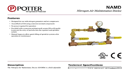
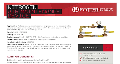
Air Maintenance Device Dry Pipe Sprinkler Systems Supervised Preaction Systems Pilot Actuated Deluge Systems Listed and FM Approved by General Air Products Inc Summit Drive Exton PA 19341 assistance visit our website for information on these and all of our products Description enclosed Automatic Air Maintenance Device is a UL and FM Approved assembly of valves nipples and actuators to automatically control the air in the piping of dry pipe sprinkler systems sprinkler systems or dry pilot actuated deluge Air Maintenance Device is designed to automatically air into the system piping at the required volume and from an air source such as air compressor air receiver tank plant air system owner s air an air receiver tank or plant air is utilized as the air source the pressure regulator in the Air AMD 1ALT Device AMD 1 level The outlet pressure of the regulator is adjustable air pressure an electrically driven air compressor is utilized as air supply source the pressure switch in the Air Device AMD 2 AMD 2ALT and AMD 3 causes the air compressor to cut in or at the minimum and maximum air pressures respectively The cut in and cut out pressures field adjustable automatic air supply is directed through a restricted in the air maintenance device so that upon of a sprinkler the air supply will not interfere the operation of the dry pipe valve by continuing to high volumes of pressurized air to the piping is a recommended safeguard that a low pressure switch alarm be installed on dry pipe systems or other air piping systems This will cause an alarm to if the pressure falls below a predetermined level Air Maintenance Device provides a continuous but air supply to the piping system activation of only one sprinkler in a dry pipe system cause the system pressure to diminish to the point the dry pipe valve will thereby filling the piping with water piping system air leaks will be compensated for by automatic air feed provided the air leaks do not the restricted air supply Data AMD 1 AMD 1ALT AMD 2 AMD 2ALT AMD 3 With Air Regulator AMD 1 AMD 1ALT Air Pressure Switch AMD 2 AMD 2ALT Operation Test FM at 35 psi air AMD 1 AMD 1ALT at 30 40 psi air AMD 2 AMD 2ALT Information Source General Air Products Inc lbs AMD 1 AMD 1ALT lbs AMD 2 AMD 2ALT AMD 3 placing an order indicate the full product name specify the quantity model and style Air Products Inc will repair and or replace any material or within a period of one year from the date of Please refer to the current price list for further of the warranty be defective Data Air Maintenance Device should be permanently to all dry pipe sprinkler systems to avoid the of false valve which may result from piping leaks gradually lowering system air Air Maintenance Device may also be utilized to control the air supply to the piping system an air supervised preaction system or to the pilot lines a dry pilot actuated deluge valve are several methods of providing a constant and supply of air to a sprinkler system as follows Compressor and Air Maintenance Device Model air compressor is connected electrically and to the trim of the dry pipe valve through an Maintenance Device equipped with a pressure switch air pressure switch continuously senses the air in the piping system and turns the compressor if the pressure drops below the cut in setting and turns compressor off if the pressure rises above the cut out The cut in pressure is usually set at the design pressure for maintaining the dry pipe valve in the position The cut out pressure should be set 10 psi above the cut in pressure the dry pipe valve is equipped with an this method of air maintenance is not The accelerator is sensitive to a 3 to 5 psi pressure drop at a rate of approximately 1 psi in 10 see AMD 1 Compressor with Air Receiver Tank and Air Device Model AMD 1 compressor tank unit is equipped with an integral switch that controls the pressure in the tank the tank pressure at a level 10 to 15 psi the designed air pressure demand of any dry pipe supplied by the air compressor tank unit The unit is mechanically connected to the of the dry pipe valve through an Air Maintenance equipped with an air pressure regulator The regulator continuously regulates the incoming from the air receiver tank and maintains the outgoing pressure at the pressure setting of the regulator within an accuracy of 1 psi The outgoing air setting is field adjustable from 5 to 75 psi If the pipe valve is equipped with an accelerator this of air maintenance is recommended Includes Non Listed Pressure Gauge AMD 1 includes a non listed pressure guage for use the regulator Gauge ships uninstalled To install the 1 8 plug on the regulator and install the gauge into the open port Air Supply and Air Maintenance Device AMD 1 plant air supply is mechanically connected to the trim the dry pipe valve through an Air Maintenance Device with an air pressure regulator The pressure continuously regulates the incoming air and the outgoing air pressure at the pressure of the regulator usually within and accuracy of 1 The outgoing air pressure setting is field adjustable 5 to 75 psi The minimum pressure in the plant air must be greater than the design air pressure by the dry pipe system since the air pressure will only regulate pressure downward Air Maintenance Device must be installed in the air line leading to the dry pipe valve trim preaction piping or dry pilot system piping The air flow the Device must be in the direction shown by the on the units The minimum pipe size is 1 2 diameter although diameter piping will provide a more rapid initial fill particularly humid environments a manual air dryer P N AD3400 should be properly between the compressor and the dry pipe valve remove moisture from the compressed air supply moisture that is allowed to back up into the cylinder may cause compressor damage room freezer room installations must have a Dry Air Pac TM which includes an AMD 1 factory for correct installation procedures AMD 1 Pressure Regulator see Fig 1 1 Close the 1 4 ball valves 8 and open the valve 7 in the Air Maintenance Device and the air supply valve in the dry pipe valve trim 2 Open the air supply control valve from the plant system or air receiver tank to pressurize the system 3 When the system is pressurized check the air gauge to verify the the pressure is at the design requirement for the system 5 Open any valve connected to the piping system as the three way valve for the air gauge on the dry valve trim just enough to slowly reduce the air Close it immediately when the pressure switch and note the cut in pressure Verify the the cut in cut out pressures meet the minimum design for the system air pressures necessary adjust the cut in or the cut out Loosen the hex nut on the cover of the switch and remove the cover Adjust the cut in by turning the Pressure Adjustment Screw in the direction Adjust pressure differential between cut in and cut out pressure by the Pressure Differential Screw Consult Factory if any doubt 6 Close the bypass valve 17 and open the two ball valves 18 The Air Maintenance Device is now service and Maintenance Air Maintenance Device does not require any scheduled maintenance However that proper operation and condition be verified as follows Verify that the 3 4 byp