Potter OSYSU-EX Explosion Proof Outside Screw and Yoke Valve Supervisory Switch

File Preview
Click below to download for free
Click below to download for free
File Data
| Name | potter-osysu-ex-explosion-proof-outside-screw-and-yoke-valve-supervisory-switch-1392758406.pdf |
|---|---|
| Type | |
| Size | 1.87 MB |
| Downloads |
Text Preview
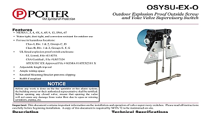
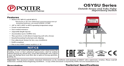
Features NEMA 1 7 9 For use in hazardous locations Listed File E14274 Certified File LR57324 EX Approved File KEMA 04ATEX2312X I Div 1 2 Groups C D II Div 1 2 Groups E F G UL listed explosion proof switch enclosure Adjustable length trip rod Ample wiring space Knurled Mounting Bracket prevents slipping Compliant any work is done on the fire sprinkler or fire alarm system building owner or their authorized representative shall be notified opening any closed valve ensure that opening the valve not cause any damage from water flow due to open or missing piping etc OSYSU EX is designed to supervise the position of an Outside Yoke type gate valve in hazardous locations The device on the valve to monitor the rising stem When properly the trip rod will be resting in a groove filed into the valve When the valve stem begins to move caused by closing the the trip rod will be pushed out of the groove and activate the To aid with installation the trip rod length is adjustable This features a UL listed explosion proof switch enclosure operation of the OSYSU EX and its associated protective system shall be inspected tested and maintained in with all applicable local and national codes and standards the Authority Having Jurisdiction manufacturer recommends or more frequently A minimum test shall consist of turning valve wheel towards the closed position The OSYSU EX shall within the first two revolutions of the wheel Fully close the and ensure that the OSYSU EX does not restore Fully open the and ensure that the OSYSU EX restores to normal only when the is fully opened the valve fully to determine that the stem threads do not the switch The switch being activated by the stem threads result in a false valve open indication This document contains important information on the installation and operation of valve supervisory switches Please read all instructions before beginning installation A copy of this document is required by NFPA 72 to be maintained on site Specifications Fig 3 lbs 0,97 kg Enclosure Aluminum Bar High Phosphorus Nickel Plated Steel Stainless Steel set of SPDT Amps at 125VAC Amps at 125VDC accept up to 14AWG wire to 140 40 to 60 I Div 1 2 Groups C D II Div 1 2 Groups E F G 1 7 9 outdoor applications use model OSYSU EX O Use 1 2 NPT threaded entrance 13 13D 13R 72 subject to change without notice PAGE 1 OF 5 Proof Outside Screw and Yoke Valve Supervisory Switch5400705 REV P 9 14Potter Electric Signal Company LLC St Louis MO Tech Support 866 956 0988 Customer Service 866 572 3005 www pottersignal comfirealarmresources com Valve Installation 1 2 12,5mm Through 2 1 2 63,5mm 1 mounting holes may be used for adjustment of switch assembly to bracket Re tighten screws to in lbs minimum Valve Installation proceed to step 7 If the valve stem is pre grooved at 1 8 minimum Remove and discard ring and roller from the trip rod With the valve in the FULL OPEN position locate the OSYSU across the valve yoke as far from the valve gland so that the loaded trip rod of the OSYSU EX is pulled against the threaded portion of the valve stem Position the OSYSU with the bracket near the handwheel as shown in Fig 1 if to avoid creating a pinch point between the wheel and OSYSU EX Loosen the locking screw that holds the trip rod in place and the rod length see Fig 3 When adjusted properly the should extend past the valve screw but not so far that it the clamp bar Tighten the locking screw to 5 in lbs to hold the trip rod in place If trip rod length is excessive loosen the locking and remove the trip rod from the trip lever Using break off the one 1 inch long notched section see 4 Reinstall trip rod and repeat Step 3 procedure Mount the OSYSU EX loosely with the carriage bolts and bar supplied On valves with limited clearance use supplied instead of the carriage bolts and clamp bar to the OSYSU EX Mark the valve stem at the center of the trip rod Remove the OSYSU EX Utilizing a 3 16 or 1 4 diameter file file a 1 8 minimum depth groove centered on the on the valve stem Deburr and smooth the edges of the to prevent damage to the valve packing and to allow the rod to move easily in and out of the groove as the valve is A groove depth of up to approximately 3 16 can make easier to install the OSYSU EX so that it does not restore it rolls over by the threads of the valve stem Mount the OSYSU EX on the valve yoke with the spring trip rod of the OSYSU EX pulled against the valve stem centered in the groove of the stem If possible position the as shown in Fig 1 to help avoid creating a pinch between the wheel and OSYSU EX Final adjustment can be made by slightly loosening the two on the bracket and using the fine adjustment feature see 1 The adjustment is correct when the switches are not with the trip rod seated in the valve stem groove and the switches activate when the trip rod moves out of the there is continuity between the COM and NO terminals the switches Tighten the adjustment screws and all mounting hardware 20 in lbs minimum Check to insure that the rod out of the groove easily and that the switches activate two turns when the valve is operated from the FULL towards the CLOSED position Reinstall the cover and tighten the cover screws the valve fully to determine that the stem threads do not the switch The switch being activated by the stem threads result in a false valve open indication PAGE 2 OF 5 5400705 REV P 9 14Potter Electric Signal Company LLC St Louis MO Tech Support 866 956 0988 Customer Service 866 572 3005 www pottersignal comOSYSU EXExplosion Proof Outside Screw and Yoke Valve Supervisory Switchfirealarmresources com 2 Valve Installation 3 Through 12 Sizes mounting holes may be used for adjustment of switch assembly to bracket Re tighten screws to in lbs minimum Valve Installation If the valve stem is pre grooved at 1 8 minimum proceed to step 6 valve is operated A groove depth of up to approximately 3 16 can it easier to install the OSYSU EX so that it does not as it rolls over by the threads of the valve stem With the valve in the FULL OPEN position locate the across the valve yoke as far from the valve so that the spring loaded trip rod of the OSYSU is pulled against the non threaded portion of the valve Position the OSYSU EX with the bracket near the as shown in Fig 2 if possible to avoid creating a point between the wheel and the OSYSU EX Mount the OSYSU EX loosely with the carriage bolts and bar supplied Loosen the locking screw that holds the trip rod in place and the rod length see Fig 3 When adjusted properly rod should extend past the valve screw but not so far that contacts the clamp bar Tighten the locking screw to 5 in minimum to hold the trip rod in place If trip rod length is excessive loosen the locking and remove the trip rod from the trip lever Using break off the one 1 inch long notched section see 4 Reinstall trip rod and repeat Step 3 procedure Mark the valve stem at the center of the trip rod Remove the OSYSU EX Utilizing a 3 8 or diameter file file a 1 8 minimum depth groove centered on mark on the valve stem Deburr and smooth the edges the groove to prevent damage to the valve packing and to the trip rod to move easily in and out of the groove as Mount the OSYSU EX on the valve yoke with the spring trip rod of the OSYSU EX pulled against the valve and centered in the groove of the stem If possible the OSYSU EX as shown in Fig 2 to help avoid a pinch point between the wheel and OSYSU EX Final adjustment can be made by slightly loosening the two on the bracket and using the fine adjustment feature Fig 2 The adjustment is correct when the swi