Potter PAD100-SB Addressable Sounder Base

File Preview
Click below to download for free
Click below to download for free
File Data
| Name | potter-pad100-sb-addressable-sounder-base-8075469231.pdf |
|---|---|
| Type | |
| Size | 1.32 MB |
| Downloads |
Text Preview
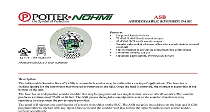
Features Integrated Sounder in base 75 dB UL 464 Listed sounder output Sounder independent of sensor allows for a single station or all call May be mapped to any device connected to the control panel Terminals accept 22 to 12 aWg wire sizes Supports Class a Class X and Class B wiring Does not require SLC Loop address UUKL Listed for Smoke Control addressable Sounder Base 6 paD100 SB is a sounder base that be utilized in a variety of applications The base has a locking for the sensor that may be used or removed in the field Once head is removed the sounder is accessible in the bottom of the unit base has an independent sounder module that may be programmed a single station zone or all call sounder The paD100 SB passes the sound pattern sent to the sounder therefore it may in any pattern the power supply provides panel will support any combination of sensors or modules on SLC The paD100 SB does not consume an address on the loop is fully programmable to operate with any input Once activated sounder will also follow the input from the power source and de accordingly VDC 33 VDC Specifications Range for SLC voltage range for current for pWR pressure level temperature relative range time number of per zone without 1 sec ma min as per UL464 to 120 0 to 49 to 93 Non condensing White 0.75 in 19mm 6.3 in 166 mm page 1 OF 2 Sounder Base 8830104 REV C 12 18Potter Electric Signal Company LLC St Louis MO Phone 800 325 3936 www pottersignal comfirealarmresources com Base Mounting should be mounted directly on the electrical box The holes are configured for a single gang double gang octagon 4 square box See Fig 1 1 the two included attached the base to detector Features of Detector Head from Base To remove the detector from the base once the locking feature has activated insert a small screwdriver into the slot on the base to the plastic tab while simultaneously turning the detector head See Fig 3 3 small screwdriver slot to remove from base the detector to the back box the mounting To remove the base cover from the lower enclosure once the locking has been activated insert a small screwdriver into the slot on on the base to push the plastic tab while simultaneously turning the head counter clockwise Information Sounder Base No Feature the Locking Feature include a locking feature that prevents removal of the and removal of the base cover without using a tool To eliminate this feature break off the locking tab and then install detector See Fig 2 2 off tab gray in image to disable feature page 2 OF 2 REV C 12 18Potter Electric Signal Company LLC St Louis MO Phone 800 325 3936 www pottersignal comPAD100 SBAddressable Sounder Base firealarmresources com