Potter PAD100-ZM Zone Module
File Preview
Click below to download for free
Click below to download for free
File Data
| Name | potter-pad100-zm-zone-module-5736089241.pdf |
|---|---|
| Type | |
| Size | 1.21 MB |
| Downloads |
Text Preview
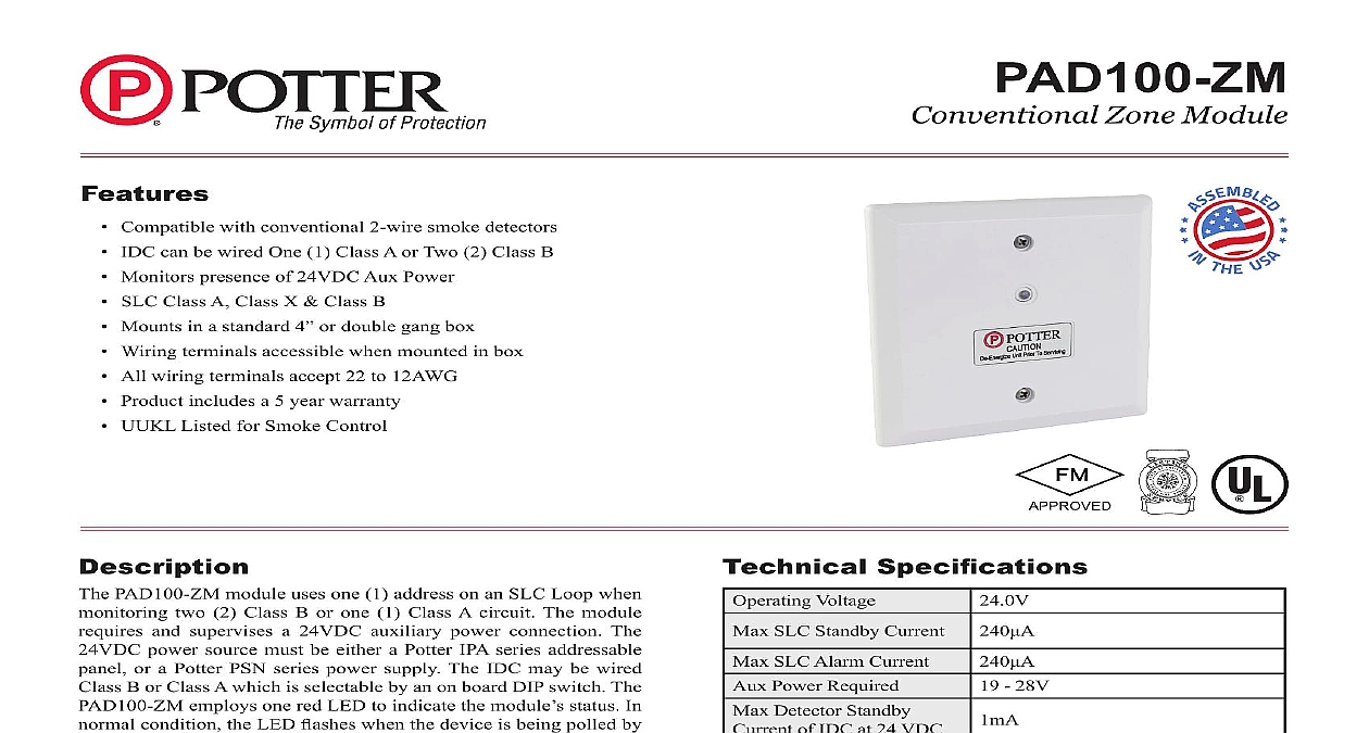
Features Compatible with conventional 2 wire smoke detectors IDC can be wired One 1 Class a or Two 2 Class B Monitors presence of 24VDC aux power SLC Class a Class X Class B Mounts in a standard 4 or double gang box Wiring terminals accessible when mounted in box all wiring terminals accept 22 to 12aWg product includes a 5 year warranty UUKL Listed for Smoke Control paD100 ZM module uses one 1 address on an SLC Loop when two 2 Class B or one 1 Class a circuit The module and supervises a 24VDC auxiliary power connection The power source must be either a potter Ipa series addressable or a potter pSN series power supply The IDC may be wired B or Class a which is selectable by an on board DIp switch The employs one red LeD to indicate the module status In condition the LED flashes when the device is being polled by control panel When a device is activated the LED will flash at a rate paD100 ZM is compatible with potter Ipa and aFC aRC addressable fire alarm control panels The PAD100 ZM is to supervise a zone of conventional 2 wire smoke detectors on Initiating Device Circuit IDC The paD100 ZM is capable of two 2 separate Class B or one 1 Class a circuits the Address addressable SLC device must be assigned an address The is set using the DIp switch located on the paD100 ZM When paD100 ZM is used to monitor two individual Class B circuits single device address is assigned each input is then identified as a of the module address For example if the address number assigned as the B1 input will be and the B2 input will be connecting a device to the SLC loop take the following to prevent potential damage to the panel or device power to the device is removed Field wiring is correctly installed Field wiring has no open or short circuits 28V Specifications Voltage SLC Standby Current SLC alarm Current power Required Detector Standby of IDC at 24 VDC Module alarm Current IDC at 24 VDC Wiring Resistance of Wiring Capacitance IDC Resistor Temperature Humidity Range no of Module per units to 120 0 to 49 to 93 non condensing Options Weight 106mm L 4.17 1.14 29mm D 4 Square or gang Box lbs page 1 OF 4 Zone Module8830085 REV D 12 18Potter Electric Signal Company LLC St Louis MO Phone 800 325 3936 www pottersignal comfirealarmresources com Using Compatible Electrical Box 1 Diagrams Class B Wiring Diagram 2 FACP OR MODULE NEXT MODULE Class A Wiring Diagram 3 FACP OR MODULE NEXT MODULE THE DIP SWITCH POSITION CLASS B WIRING RESISTOR OHM W 3005013 RESISTOR OHM W 3005013 24 VOLT POWER FACP THE DIP SWITCH POSITION CLASS A WIRING RESISTOR NOT REQUIRED VOLT POWER FROM FACP PREVIOUS MODULE VOLT POWER TO FACP NEXT MODULE Information Zone Module No page 2 OF 4 REV D 12 18Potter Electric Signal Company LLC St Louis MO Phone 800 325 3936 www pottersignal comPAD100 ZMConventional Zone Modulefirealarmresources com 2 Wire Smoke Detectors Bases Model Model SENSOR Brk Max No Of Detectors Per Zone is 10 SYSTEM Max No Of Detectors Per Zone is 11 Max No Of Detectors Per Zone is 20 Max No Of Detectors Per Zone is 20 page 3 OF 4 REV D 12 18Potter Electric Signal Company LLC St Louis MO Phone 800 325 3936 www pottersignal comPAD100 ZMConventional Zone Modulefirealarmresources com Model Model Max No Of Detectors Per Zone is 14 of the above Fenwal detectors and bases can be used in any combination Base Adaptor 70 501000 003 Identifier MAFE1 for series 70 201000 Bases Models 001 002 003 and 005 Housing with Detector Base DH 51 Identifier DH22FE5 for CPD 7051 and PSD 7155 detectors only Max No Of Detectors Per Zone is 25 HOCHIKI HOCHIKI HOCHIKI If using a mix of System Sensor and other smoke detectors a maximum of 20 detectors shall be permitted HOCHIKI HOCHIKI HOCHIKI HOCHIKI HOCHIKI HOCHIKI page 4 OF 4 REV D 12 18Potter Electric Signal Company LLC St Louis MO Phone 800 325 3936 www pottersignal comPAD100 ZMConventional Zone Modulefirealarmresources com