Potter PCMPK Series Corrosion Monitoring Probe Kit

File Preview
Click below to download for free
Click below to download for free
File Data
| Name | potter-pcmpk-series-corrosion-monitoring-probe-kit-5248319706.pdf |
|---|---|
| Type | |
| Size | 1.10 MB |
| Downloads |
Text Preview
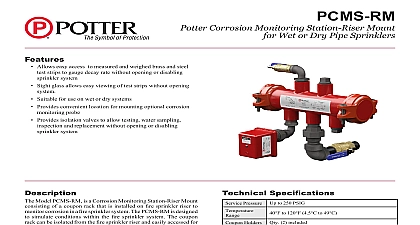
PCMPK CORROSION PROBE KIT Pipe Systems Model PCMS RM Turn the 1 isolation valve to the closed position to isolate the rack from the re sprinkler system Verify that the drain valve is in the closed position Remove drain plug Relieve system pressure from the coupon rack by opening the valve slowly Drain the water from the coupon rack through drain valve into container Note The water in the coupon will be pressurized to the system pressure Close the valve Re install the plug into drain valve Do not handle probe with bare hands Remove the corrosion probe from the sealed packaging using the latex gloves and carefully remove the cardboard protection sleeve Te on tape to the 1 NPT male pipe threads and install the into bottom outlet 3 as indicated in the probe installation on the coupon rack label Apply Te on tape to the NPT male pipe thread on the pressure Install the pressure switch into the bottom outlet 3 monitoring probe using Te on tape on the provided nipple and 90 street elbow as illustrated in Fig 4 It is not recommended to mount the pressure switch in an position Connect the wiring from the re panel to the pressure switch accordance to the PS10 Pressure Switch Bulletin 5400928 the re system administrator to enable the re panel zone to the probe On some versions it may be necessary to install ttings to supply air to the coupon rack through the air inlet isolation With the coupon rack isolation valve closed to the system and coupon rack drain valve closed and plugged pre charge coupon rack with air through the air inlet isolation valve to the system water pressure Open the coupon isolation valve and check the water level in the coupon through the end sight glass The water level needs to be at the centerline of the pipe coupon rack Add air through the air inlet isolation valve to lower the level or relieve air to raise the water to the correct centerline Close the air inlet isolation valve after the correct water has been maintained Be sure to leave the coupon rack valve open to the re sprinkler system Verify that all are in the correct position and the corrosion monitoring is free of any leaks Pipe Systems Model PCMS PCMS LP Turn the two 1 ball valves PCMS or butter y isolation valve to closed position to isolate the coupon rack from the re sprinkler system Verify that the drain valve is in the closed position Remove drain plug Relieve system pressure from the coupon rack by opening the valve slowly Drain the water from the coupon rack through drain valve into container Note The water in the coupon will be pressurized to the system pressure Close the valve Re install the plug into drain valve pending kit shown use on RM Riser Mount and Dry Pipe ceiling mount models Not use on RM Models read and follow the instructions and procedures provided this and referenced documents Failure to do so will inhibit our to provide accurate and complete test results not handle the probes with your bare hands Use the latex provided PCMPK consists of the necessary corrosion monitoring probes and switches that when added to the Potter Corrosion Monitoring provides noti cation to the re sprinkler administrator when may be an excessive amount of corrosion taking place in the piping The corrosion monitoring probe has a precision thin thickness which will eventually corrode through allowing the water or air pressure to enter into the probe and actuate the switch When the pressure switch is wired to the building re alarm panel a supervisory or trouble signal is generated notifying re sprinkler administrator This is the noti cation to remove the coupons that were installed at the same time as the probe s for on the condition of sprinkler piping The corrosion monitoring are single use devices and must be replaced upon the installation new test coupons Includes corrosion monitoring probe and 1 pressure switch for PCMPK 1 corrosion monitoring probes and 2 pressure switches for PCMPK 2 Bottom mounting pressure switch ttings 1 union 1 90 street and 1 nipple One pair of latex gloves Required Pipe wrench or 14 adjustable wrench to remove and replace probes Container used to drain water from the isolated coupon rack Te on tape Electric Signal Company LLC St Louis MO Phone 866 956 0988 Canada 888 882 1833 www pottersignal com IN U S A 5401211 REV F 1 OF 3 Do not handle probes with bare hands Remove the corrosion probes from the sealed packaging using the latex gloves and carefully remove the cardboard protection sleeve Te on tape to the 1 NPT male pipe threads and install the into top outlet 3 and bottom outlet 6 as indicated in the installation diagram on the coupon rack label Apply Te on tape to the NPT male pipe thread on the pressure Install a pressure switch directly into the top outlet corrosion monitoring probe It is recommended that a union be added for easier future probe replacement eliminates need for the pressure switch wiring to be disconnected during replacement If ceiling clearance is an issue with the top pressure switch it can be hard piped up to three feet Install a pressure switch into the bottom outlet 6 corrosion probe using Te on tape on the provided union nipple and street elbow as illustrated in Fig 2 or Fig 3 It is not recommended to mount the pressure switch in an position Connect the wiring from the re panel to the pressure switch accordance to the PS10 Pressure Switch Bulletin 5400928 the re system administrator to enable the re panel connected to the probe This zone should be identi ed as a or trouble zone not an alarm zone Verify that the isolation valve s are in the open position and corrosion monitoring station is free of any leaks Be sure leave the coupon rack isolation valve s open to the re system Pipe Systems Model DPCMS DPCMS RM PCMS RM Notify the re system administrator and close the system control Shut down the supervisory air supply and relieve system air through the inspectors test valve When using the DPCMS RM or PCMS RM it may not necessary to relieve air pressure from the entire system The has a drain valve to vent pressure Use extreme care loosen a tting in the DPCMS RM to relieve pressure CORROSION PROBE KIT Do not handle probe with bare hands Remove the corrosion probe from the sealed packaging using the latex gloves and carefully remove the cardboard protection sleeve Te on tape to the 1 NPT male thread on the probe and the probe into the bottom outlet as indicated in the probe diagram on the coupon rack label Apply Te on tape to the NPT male pipe thread on the pressure Install the pressure switch into the bottom Outlet 4 monitoring probe using Te on tape on the provided nipple and 90 street elbow It is not recommended to mount the pressure switch in an position Connect the wiring from the re panel to the pressure switch in to the PS10 Pressure Switch Bulletin Notify the re administrator to enable the re panel zone connected to the This zone should be identi ed as a supervisory or trouble not an alarm zone Place the system back in service Verify that all valves are in the proper position and the corrosion station is free of any leaks Be sure to leave the coupon isolation valve s open to the re sprinkler system 1 Corrosion Monitoring Probe 1176 5 NPT FEMALE FOR PRESSURE 2 PCMS Assembly 3 PCMS LP Assembly Obsolete IN U S A 5401211 REV F 2 OF 3 4 PCMS RM Assembly 5 DPCMS Assembly Obsolete CORROSION PROBE KIT 6 DPCMS R