Potter PCVS-CRH Corrosion Resistant Control Valve Supervisory Switch
File Preview
Click below to download for free
Click below to download for free
File Data
| Name | potter-pcvs-crh-corrosion-resistant-control-valve-supervisory-switch-7104359268.pdf |
|---|---|
| Type | |
| Size | 1.98 MB |
| Downloads |
Text Preview
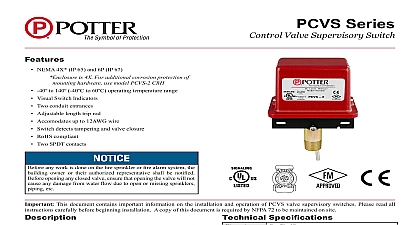
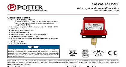
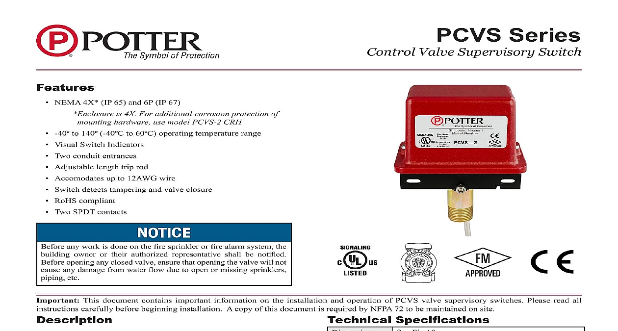
Features NEMA 4X IP 65 and 6P IP 67 is 4X For additional corrosion protection of mounting hardware use model PCVS 2 CRH 40 to 140 40 to 60 operating temperature range Visual Switch Indicators Two conduit entrances Adjustable length trip rod Accomodates up to 12AWG wire Switch detects tampering and valve closure RoHS compliant Two SPDT contacts owner or their authorized representative shall be notified This Specifications Model PCVS is a weather proof and tamper resistant switch for the open position of fire sprinkler control valves of the are provided which will operate when the valve position is unit mounts in a 1 2 NPT tapped hole in the post indicator or valve housing The device is engaged by the indicating of the post indicator or the operating mechanism of the cover is held in place by two tamper resistant screws that require a Tamper Fig 10 Die Cast Finish Red Powder Coat Resistant Screws Cover Tamper Switch Available Two Sets of SPDT Form C mAmps minimum at 24 VDC F to 140 40 to 60 4X IP 65 and NEMA 6P Enclosure IP67 suitably rated conduit and connector or Outdoor Use See PIVSU EX Bulletin for Hazardous locations operation of the PCVS and its associated protective monitoring shall be tested upon completion of the installation and in national codes and standards and or the Authority Having Juris test shall consist of turning the valve operating mechanism Use PAGE 1 OF 7 SeriesControl Valve Supervisory Switch5401526 REV F 8 15Potter Electric Signal Company LLC St Louis MO Tech Support 866 956 0988 Customer Service 866 572 3005 www pottersignal comfirealarmresources com Of Operation Window Installation and Moving Hood Installation 1 2 Moves Up as Valve is Shut Moves Down as Valve is Shut to the approval of the having jurisdiction the Plate Replaces Glass Assembly PAGE 2 OF 7 REV F 8 15Potter Electric Signal Company LLC St Louis MO Tech Support 866 956 0988 Customer Service 866 572 3005 www pottersignal comPCVS SeriesControl Valve Supervisory Switchfirealarmresources com Installations On Post Indicator Valve Housings 3 4 moves up moves down Position the valve to fully open should appear in the valve housing is predrilled with a target assembly consultation with valve manufacturer is the distance from the bottom of the head to the part of the target assembly that will contact the trip rod the target down as the valve was closed measure the distance the bottom of the head to the upper portion of the assembly that will contact the trip rod of the PCVS Fig 4 Add 1 8 3,2mm to this measurement Mark on the side that coincides with the portion of the Replace Loosen Screw Screw the nipple into the 1 2 NPT hole in the valve housing a scale or probe thru the nipple to measure the distance In some cases it may be necessary to attach an bracket to the target assembly to engage the PCVS trip Using Loosen Partially