Potter PFC-200RC Fire Alarm Control and Extinguishing Agent Releasing Panel
File Preview
Click below to download for free
Click below to download for free
File Data
| Name | potter-pfc-200rc-fire-alarm-control-and-extinguishing-agent-releasing-panel-1826795403.pdf |
|---|---|
| Type | |
| Size | 929.15 KB |
| Downloads |
Text Preview
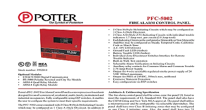
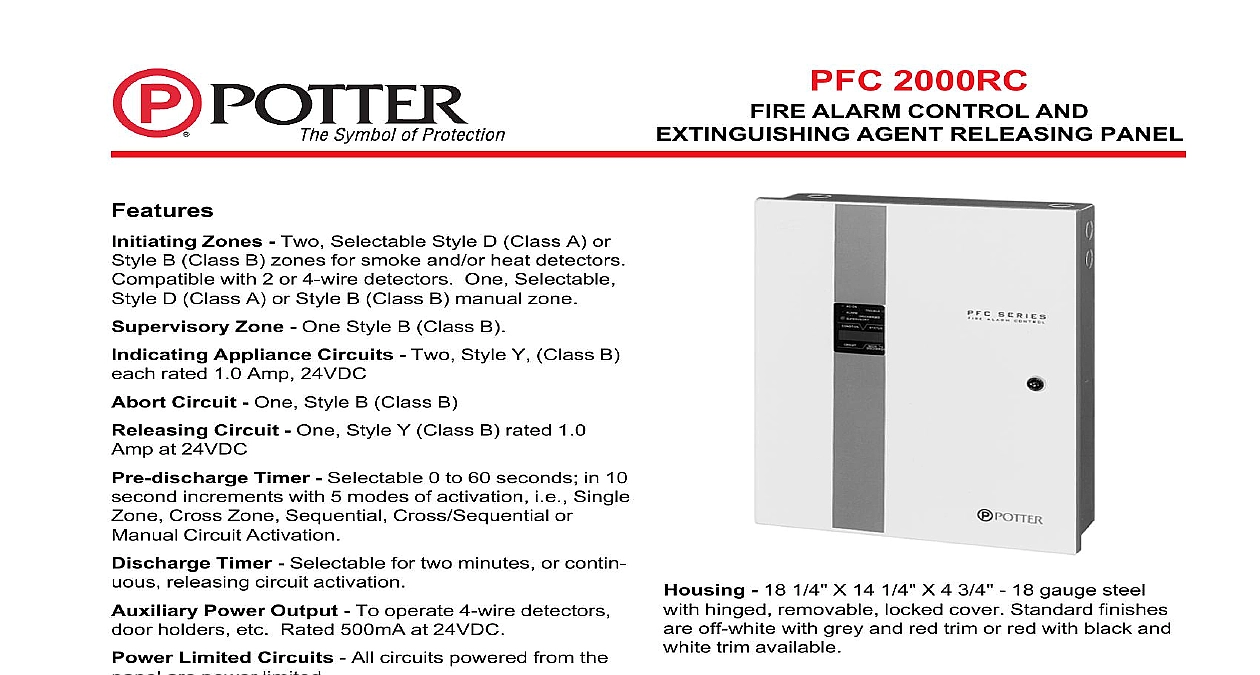
PFC 2000RC ALARM CONTROL AND AGENT RELEASING PANEL 18 1 4 X 14 1 4 X 4 3 4 18 gauge steel hinged removable locked cover Standard finishes off white with grey and red trim or red with black and trim available No Information 2000RC Fire Control Panel Cabinet 2000RC Fire Control Panel Cabinet for semi flush mounting White for semi flush mounting Red Battery 4.0AH Battery 8.0AH Battery 12.0AH Circuit Board Module Spare Supply Module Spare of line Resistor Spare Operation and Instruction Manual 5403521 DPDT Relay Assembly Zones Two Selectable Style D Class A or B Class B zones for smoke and or heat detectors with 2 or 4 wire detectors One Selectable D Class A or Style B Class B manual zone Zone One Style B Class B Appliance Circuits Two Style Y Class B rated 1.0 Amp 24VDC Circuit One Style B Class B Circuit One Style Y Class B rated 1.0 at 24VDC Timer Selectable 0 to 60 seconds in 10 increments with 5 modes of activation i e Single Cross Zone Sequential Cross Sequential or Circuit Activation Timer Selectable for two minutes or contin releasing circuit activation Power Output To operate 4 wire detectors holders etc Rated 500mA at 24VDC Limited Circuits All circuits powered from the are power limited Man Test Feature Panel automatically resets in this mode Display Panel 32 character alpha numeric display backlight indicates all alarm trouble and supervisory in an English format Buzzer Built in Switch One switch silences alarm or trouble Delay 3 second delay prevents accidental reset Contacts One set each for trouble and alarm 2.0 Amps at 30VDC Output for optional alarm Battery Available for 24 60 or 90 hours and Approvals UL FM NYMEA and CSFM Use Designed to meet NFPA Standards 12 12B 13 17 and 72 Electric Signal Company 2081 Craig Road St Louis MO 63146 4161 Phone 800 325 3936 Canada 888 882 1833 www pottersignal com IN USA 1 OF 2 8900058 REV H 2000RC ALARM CONTROL AND AGENT RELEASING PANEL Specifications control panel for the fire alarm extinguishing agent system shall be a model PFC 2000RC manu by Potter Electric Signal Co of St Louis MO It be listed by Underwriters Laboratories Inc and by Factory Mutual Research Corporation and with National Fire Protection Association Stan 12 12A 12B 13 17 and 72 housing shall be 18 gauge sheet steel and shall have hinged removable door with a key lock The finish be baked enamel An optional trim bezel shall be for semi flush mounting The unit shall be based and the main circuit board module be removable without disconnecting the field wiring combination power supply battery charger shall be as a part of the control Adequate space shall provided for standby batteries that are capable of the system for up to 24 hours A matching cabinet shall be available to house batteries of operating the system for up to 90 hours All protection devices shall be resettable type breakers All circuits powered from the control shall meet Underwriters Laboratories Inc require for power limited circuits Regulated 24 Volts DC at 5 Amp shall be available for the operation of 4 detectors or other auxiliary devices supervised signal initiating device circuits for smoke heat detectors with a capacity of 25 100 2 wire shall be provided A separate manual station shall also be provided Each circuit shall be switch to be Style D Class A or Style B Class B supervised signal indicating device circuits shall be that reverse polarity when an alarm condition These circuits shall supply regulated 24V DC at 1.0 Amp to the indicating devices separate supervised Style B Class B supervisory shall be provided for the connection of such items valve pressure or temperature monitoring switches of this circuit shall result in a distinct superviso indication supervised extinguishing agent releasing circuit shall provided that reverses polarity when a releasing occurs This circuit shall be rated at 24VDC Amp continuous or 3 Amps momentary following visual indicators shall be visible with the closed AC ON Green LED ALARM Red LED Yellow LED TROUBLE Yellow LED DISCHARGED Red LED A 32 character alpha liquid crystal display with backlight shall also be to display in an English format the condition and circuit for all Alarm Trouble and Supervisory The time to discharge will be displayed whenev the pre discharge timer is activated unit shall contain the following Control Switches A Silence Switch that silences the alarm indicating and Trouble Buzzer a Reset Switch that must be for 3 seconds to prevent accidental resetting a Test that turns on all Alarm and Trouble indicators and a Zone Disable Switch for each zone a Releas Circuit Disable Switch and an Auto Reset Switch that the latching function making a Man Test pre discharge timer that is switch selectable from 0 to seconds in 10 second increments shall be provided timer shall have 5 switch selectable modes of Single Zone Cross Zone Sequential Cross or Manual Circuit A discharge timer with periods of 2 minutes or continuous shall also provided set of form C SPDT contacts shall be provided for system alarm and system trouble The contacts be rated at 2 Amps 30 Volts end of the line resistors for all circuits shall be the value All selectable operating modes shall be selectable and the panel shall be free of program jumpers IN USA 8900058 REV H 2 OF 2