Potter PS10 Series Pressure Type Waterflow Switch

File Preview
Click below to download for free
Click below to download for free
File Data
| Name | potter-ps10-series-pressure-type-waterflow-switch-1092675438.pdf |
|---|---|
| Type | |
| Size | 1.47 MB |
| Downloads |
Text Preview
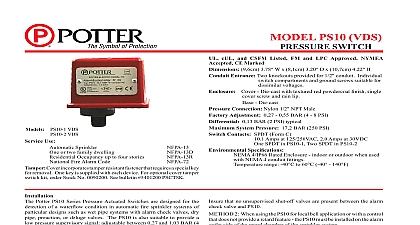
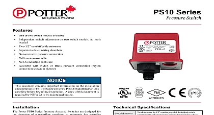
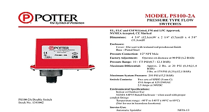
Independent switch adjustment on two switch models no tools One or two switch models available Two 1 2 conduit cable entrances Separate isolated wiring chambers Non corrosive pressure connection VdS version available Non Conductive enclosure document contains important information on the installation operation of PS10 pressure switches Please read all instructions before beginning installation A copy of this document is by NFPA 72 to be maintained on site Potter PS10 Series Pressure Actuated Switches are designed for detection of a waterflow condition in automatic fire sprinkler of particular designs such as wet pipe systems with alarm valves dry pipe preaction or deluge valves The PS10 is suitable to provide a low pressure supervisory signal adjustable 4 and 15 psi 0,27 and 1,03 bar Apply Teflon tape to the threaded male connection on the device not use pipe dope Device should be mounted in the upright position threaded connection Tighten the device using a wrench on the flats on the device Instructions Remove the tamper resistant screw with the special key Carefully place a screwdriver on the edge of the knockout and apply a force sufficient to dislodge the knockout plug Fig 9 Run wires through an approved conduit connector and affix the to the device NEMA 4 rated conduit and fittings are for outdoor use Connect the wires to the appropriate terminal connections for the intended See Figures 2,4,5 and 6 See Fig 7 for two one conduit wiring Specifications Entrances Ratings Tamper knockouts for 1 2 conduit provided Individual switch and ground screw suitable for dissimilar voltages Form C Amps at 125 250VAC 2.0 Amps at 30VDC SPDT in PS10 1 Two SPDT in PS10 2 incorporates tamper resistant fastener that requires a special for removal One key is supplied with each device psi 0,13 bar typical Weather UV Flame Resistant High Impact Composite Die Cast parts have corrosion resistant finishes F to 140 40 to 60 4 IP66 Rated Enclosure indoor or outdoor when used with 4 conduit fittings 8 psi 0,27 0,55 bar psi 20,68 bar Adjustment System Connection Nylon 1 2 NPT male Range Use psi 0,27 1,03 bar 13 13D 13R 72 subject to change without notice PAGE 1 OF 4 SeriesPressure Switch5400928 REV E 2 20Potter Electric Signal Company LLC St Louis MO Phone 800 325 3936 www pottersignal comfirealarmresources com and Adjustment Testing the PS10 may activate other system connected devices The operation of the pressure alarm switch should be tested upon completion of and periodically thereafter in accordance with the applicable NFPA codes and standards and or the authority having jurisdiction manufacturer quarterly or more frequently There should be no need to adjust the PS10 when it is used as a pressure type waterflow indicator It is factory set comply with UL and FM standards System 1 When using PS10 and control unit with retard connect PS10 into alarm port piping on the input side of retard chamber and electrically PS10 to control unit that provides a retard to compensate for surges Insure that no unsupervised shut off valves are present between the alarm valve and PS10 2 When using the PS10 for local bell application or with a control that does not provide a retard feature the PS10 must be installed on the outlet side of the retard chamber of the sprinkler system Accomplished by opening the inspector end of line test valve Allow time to compensate for system or control retard Method 2 is not applicable for remote station service use if there is an unsupervised shut off valve between the alarm check valve and the PS10 System With Excess Pressure PS10 into alarm port piping extending from alarm check valve Retard provisions are not required Insure that no unsupervised shut off valves present between the alarm check valve and the PS10 Accomplished by opening the water by pass test valve or the inspector end of line test valve When using end of line test allow time for pressure to bleed off System PS10 into alarm port piping that extends from the intermediate chamber of the alarm check valve Install on the outlet side of the in line check of the alarm port piping Insure that no unsupervised shut off valves are present between the alarm check valve and the PS10 Accomplished by opening the water by pass test valve The above tests may also activate any other circuit closer or water motor gongs that are present on the system 1 Clamping Plate Terminal 2 NPT To prevent leakage apply Teflon tape sealant to male threads only 930 1 uninsulated section of a single conductor should not be looped around the and serve as two separate connections The wire must be severed providing supervision of the connection in the event that the wire dislodged from under the terminal PAGE 2 OF 4 REV E 2 20Potter Electric Signal Company LLC St Louis MO Phone 800 325 3936 www pottersignal comPS10 SeriesPressure Switchfirealarmresources com Sprinkler Applications 3 SYSTEM WITH PRESSURE SYSTEM WITHOUT PRESSURE SYSTEM Y Y Y 923 2AA of any shutoff valves between the alarm check valve and the PS10 will render the PS10 inoperative To comply with NFPA 72 any such valve shall be supervised with a supervisory switch such as Potter Model RBVS Pressure Signal Connection 4 Signal Connection 5 FIRE ALARM PANEL FIRE ALARM PANEL Bell For Waterflow Connection 6 DC NEUTRAL AC LINE LOAD DC HOT AC 928 1 928 2 928 3 Conduit Wiring 7 out thin section of divider to provide path for wires when wiring switches from one conduit entrance Operation 8 928 4 PRESSURE APPLIED 1 2 PRESSURE APPLIED Common Closed when installed under normal system pressure Open when installed under normal system Closes on pressure drop Use for low pressure supervision Open with no pressure supplied Closes upon detection of pressure Use for waterflow indication Closed with no pressure applied 1 2 PAGE 3 OF 4 REV E 2 20Potter Electric Signal Company LLC St Louis MO Phone 800 325 3936 www pottersignal comPS10 SeriesPressure Switchfirealarmresources com Knockouts 9 Specifications Type Waterflow Switch type waterflow switches shall be a Model PS10 as by Potter Electric Signal Company St Louis MO and be installed on the fire sprinkler system as shown and or specified shall be provided with a NPT male pressure connection shall be connected to the alarm port outlet of Wet Pipe Alarm Dry Pipe Valves Pre Action Valves or Deluge Valves The switch shall be actuated when the alarm line pressure reaches 8 psi 0,27 0,55 bar type waterflow switches shall have a maximum service rating of 300 psi 20,68 bar and shall be factory adjusted to on a pressure increase of 4 8 psi 0,27 0,55 bar switch shall have one or two form C contacts switch contact 10.1 Amps at 125 250 VAC 2.0 Amps at 30 VDC type waterflow switches shall have two conduit entrances for each individual