Potter PS120A Series High Low Pressure Switch

File Preview
Click below to download for free
Click below to download for free
File Data
| Name | potter-ps120a-series-high-low-pressure-switch-4751069832.pdf |
|---|---|
| Type | |
| Size | 676.73 KB |
| Downloads |
Text Preview
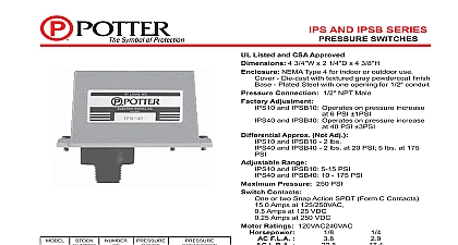
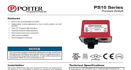
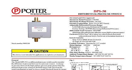
MODEL PS120A SWITCHES cUL and CSFM Listed FM and LPC Approved NYMEA CE Marked 3 4 12,1cm W x 2 1 4 5,7cm D x 4 3 8 Die cast with textured red powdercoat nish Plated Steel Connection 1 2 NPT Male Adjustment Operates on decrease at 110 PSI 7,6 BAR Operates on increase at 130 PSI 9 BAR and on at 110 PSI 7,6 BAR Range 10 175 PSI 0,7 12,1 BAR Differential Approx 2 lbs at 20 PSI 0,14 1,4 BAR 5 lbs at 175 PSI 0,35 12,1 BAR System Pressure 250 PSI 17,2 BAR Contacts SPDT Form C Amps at 125 250VAC 2.5 Amps at 30VDC set in PS120 1A Two sets in PS120 2A Speci cations or outdoor use 4 IP55 Rated Enclosure when used with proper conduit ttings Range 40 to 140 40 to 60 for use in hazardous locations Use Sprinkler or two family dwelling occupancy up to four stories Fire Alarm Code Cover incorporates tamper resistant fasteners that require a key for removal One key is supplied with each device For cover tamper switch kit order Stock No 0090134 for testing the unit can be accomplished with the installation a Potter Bleeder Valve Model BVL in the line to the PS120A The operation of the pressure supervisory switch should be upon completion of installation and periodically thereafter in with the applicable NFPA codes and standards and or the having jurisdiction manufacturer recommends quarterly or frequently Testing the PS120A may activate other system connected Single Switch Stock No 1341201 Double Switch Stock No 1341202 Potter PS120A Series are pressure actuated switches designed to detect a 10 PSI 0,7 BAR increase and or decrease from system pressure in automatic re sprinkler systems applications are pressure supervision in systems with excess AND TEST PROCEDURES Device should be mounted in upright position threaded down NEMA type 4 conduit hub for outdoor installations System with excess pressure Connect PS120A in the excess line on the system side of any shut off or check valve Electric Signal Company 2081 Craig Road St Louis MO 63146 4161 Phone 800 325 3936 Canada 888 882 1833 www pottersignal com IN USA 8810004 REV V 5400926 6 06 PAGE 1 OF 2 PS120A SWITCHES PREVENT LEAKAGE APPLY TEFLON TAPE TO MALE THREADS ONLY OF PIPE JOINT CEMENT MAY RESULT IN OF APERTURE AND LOSS OF ADJUSTMENTS The operating point of the switch or on the PS120 2A can be adjusted to any point between and 175 PSI by turning the adjustment knob s clockwise to the actuation point and counter clockwise to lower the point In the case of the PS120 2A the two switches completely independently of one another and each may be adjusted to actuate at any point the system requires adjustment should be made with a pressure gauge Y 926 1 Sprinkler Application Switch Terminations Electrical Connections Information Pressure switch with one set SPDT contacts Pressure switch with two sets SPDT contacts Valve Key Tamper Switch Valve tamper switch No High switch changes with pressure increase Low switch changes with decrease Terminal Connections Clamping Plate Terminal I N N uninsulated section of a single conductor not be looped around the terminal serve as two separate connections The must be severed thereby providing of the connection in the event the wire becomes dislodged from under terminal I N 923 3 Speci cations supervisory switch shall be a Model PS120A as manufactured by Potter Electric Signal Co of St Louis MO and shall be installed on the sprinkler systems shown on the drawings and or as speci ed herein shall be provided with a 1 2 NPT male pressure connection and shall be connected into the excess pressure supply line on the system side of any shut off A Model BVL Bleeder Valve as supplied by Potter Electric Signal Co of St Louis MO or equivalent shall be connected in line with the PS120A to provide means of testing the operation of the supervisory switch switch unit shall contain SPDT Form C switch es One switch shall operate at a pressure decrease of 10 PSI 0,7 BAR from normal If two switches are the second switch shall operate at a pressure increase of 10 PSI 0,7 BAR from normal Switch contacts shall be rated at 15.0 Amps at 125 250VAC and Amps at 30VDC The unit shall have a maximum pressure rating of 250 PSI 17,2 BAR and shall be adjustable from 10 to 175 PSI 0,7 12,1 BAR switch housing shall be weatherproof and oil resistant The cover shall incorporate tamper resistant screws unit shall be UL and CSFM Listed FM and LPC Approved and NYMEA Accepted IN USA 8810004 REV V 5400926 6 06 PAGE 2 OF 2


