Potter PVX-RM REMOTE MICROPHONE INSTALLATION INSTRUCTIONS

File Preview
Click below to download for free
Click below to download for free
File Data
| Name | potter-pvx-rm-remote-microphone-installation-instructions-1923046857.pdf |
|---|---|
| Type | |
| Size | 610.32 KB |
| Downloads |
Text Preview
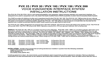
PVX RM MICROPHONE INSTRUCTIONS PVX RM is a supervised remote microphone panel for use with the PVX 25 50 100 voice evacuation The purpose is to allow emergency voice messages to be made over the system speakers from location remote from the PVX 25 50 100 PVX RM connects via 3 pair shielded cable to the PVX SC supervisory card which is mounted within PVX 25 50 100 Fault conditions in the wiring or in the remote microphone circuitry are reported to the through the same supervisory path as the PVX 25 50 100 the PVX RM microphone is keyed during an alarm condition the alarm signal and digital message be interrupted and live voice messages can be broadcast normal standby the microphone can be to make announcements at any time Any time an PVX RM is keyed the In Use LED will light on all PVX RMs the other units will be disabled This is to insure that only one operator is able to page the system If the master microphone in the PVX 25 50 100 is keyed it will override any remote must insure that all wiring and devices installed in system meet the following standards Electrical Code NFPA 70 Standard 72 Safety Code NFPA 101 equipment in a clean dry environment avoid installation where equipment could be to vibration Remove electronic assemblies from the enclosure prior to any drilling punching of the enclosure Where possible make all cable entries from the rear or sides making any modifications to the enclosure be certain that they will not interfere with all power is off before making any wire connections to wiring and terminal designation diagrams Use 3 pair shielded wire 22 AWG min from the PVX 25 50 100 to the remote microphone location Attach snap track to the PVX 25 50 100 cabinet Mount PVX SC Supervisory Card to snap track May factory mounted and wired Make wiring connections as shown on WD 1 Where multiple PVX RM units are used insure EOLR is used on last unit only Apply power to test Test systems primary microphone Test the PVX RM remote microphone Activate an Alarm PVX 25 50 100 to insure that tone and message are broadcast 1 5015 REV C technical assistance please call Phantom Dr St Louis Missouri 63042 Detail Fig 1 pair Shielded AWG UNITS ON LAST UNIT ONLY 25 50 100 11 10 6 2 1 8 Line Resistance last PVX RM is 100 line 5000 of 22AWG wiring is Power Limited must be mounted same enclosure as the 25 50 100 or in another UL Listed cabinet within in conduit PVX SC must be mounted using metal standoffs or Earth ground connection must be made to TB2 7 faults are indicated at 10K impedance or less DESIGNATIONS RED 1 MIC PTT 24 10mA 2 V 24 VDC 0.10A 3 PTT 24V 10mA 4 Audio 1Vrms 10mA 5 Ckt Neg 6 Fault 24V 10mA 7 Earth Ground 1 V 24 VDC 0.044A 2 Ckt Neg 3 Fault 24V 4 PTT 24V 10mA 5 Audio 1Vrms is a 6 3 SIP 10K Resistor Network be installed on last PVX RM only line resistance is dependent on Down 10mA of devices loading the line PVX RM 100 Max Line Resistance PVX RM 80 Max Line Resistance PVX RM 65 Max Line Resistance PVX RM 50 Max Line Resistance than 5 PVX RMs is not recommended 1 V 24 VDC 2 Ckt Neg 3 Fault 4 PTT 5 Audio 1Vrms 1 Yellow Yellow Use Red Gain clockwise increase position modular jack to microphone Voltage 24 VDC Current 0.033A DC Standby DC Active Voltage 24 VDC Current 0.033A DC Standby 0.044A DC Active 25 50 100 wiring from PVX SC is Power Limited wiring must be routed to maintain minimum from any Non Power Limited wiring cabling is Non Power Limited Not a of Battery cabling any Power Limited wiring When circuits are Power Limited Power Limited cable as detailed in the Electrical Code Article 760 such FPL or FPLP type cabling wiring connections wire clamp screw 14 18 AWG wire clamp screw 12 18 AWG wire entry terminal 18 26 AWG gauge determined by circuit load 1 5015 REV C technical assistance please call Phantom Dr St Louis Missouri 63042