Potter SignaLink™ Bridge Wireless Supervisory System

File Preview
Click below to download for free
Click below to download for free
File Data
| Name | potter-signalink-bridge-wireless-supervisory-system-4367105892.pdf |
|---|---|
| Type | |
| Size | 1.46 MB |
| Downloads |
Text Preview
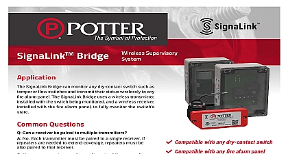
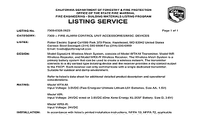
Features 864 10th edition and ULC S527 Listed supervised wireless communication bridge between all dry devices GHz communication format works on any dry contact product not listed as explosion provides dry contact output compatible with any fire panel alarm system does not require resetting or silencing allowing it to be remotely from the FACP the need for extensive wiring conduits is powered by a listed supply it can support multiple transmitters device includes a cover tamper pry off tamper switch an LED to when it is transmitting and an LED to aid in resetting the battery see fig 3 For mounting to a post use the optional post mounting kit see fig 6 Specifications Transmitter Connection Limitations Circuit Current Circuit Voltage This document contains important information on the installation and operation of the Potter SignaLink Wireless products Please read all carefully before beginning installation A copy of this document is required by NFPA 72 to be maintained on site Potter SignaLink Bridge is a fully supervised wireless bridge to be attached to any non explosion proof dry contact sprinkler devices It removes the need to hard wire sprinkler devices each other and operates on a 2.4 GHz frequency Devices are able to with each other up to a maximum of 800 All enclosures are and UV resistant polycarbonate There are no external antennas antenna is incorporated into the circuit board of each device Model WTX M transmitter enclosure has a threaded nipple O ring and locking nut mounting directly to the conduit entrance of any dry contact device listed as explosion proof The transmitter provides two flying leads connection to the normally open contacts of any listed dry contact fire device The connection is supervised for opens and shorts using the 5.1k ohm End Of Line Resistor The transmitter does not latch follows the status of the sprinkler switch it is connected to The unit is by two 2 AA size 1.5 volt Lithium Iron Disulfide batteries The includes a cover tamper switch as well as an LED to indicate when battery meter has been reset See fig 1 Model WRX R receiver contains a fail safe dry contact output than can be monitored any UL listed fire panel zone or monitor module The receiver enclosure an opening for 1 2 conduit The receiver follows the status of the so there is no reset switch no sounder and no need for human The receiver can be powered by the auxiliary power of the panel or UL 864 or UL 1481 listed 24 VDC supply with regulated power output and battery backup See ordering information on 10 for optional power supply The receiver contains Individual for Power Alarm Supervisory transmitter or repeater trouble Communication Error Low Battery and EOLR trouble to aid in See fig 2 Model WR repeater can be powered by one 3.6 volt D size Lithium Thionyl or by the auxiliary power of the fire panel or UL 864 or UL 1481 24 VDC supply with battery backup See ordering information on 10 for optional power supply Per UL 864 if the repeater is powered batteries it must be dedicated to only one transmitter repeater pair If the NPT male Fig 5 and Impact resistant Polycarbonate NEMA 4 IP66 40 to 150 40 to 66 VDC AA size Energizer 1.5 volt Lithium Iron Disulfide battery L91 3000 mAh Ambient noise level allowed 37 dBm 13 13D 13R and 72 lbs 0.23 KG for 1 2 conduit terminals for 12 22 AWG wires Alarm Supervisory Relay 1A at 30 VDC Fig 4 and Impact resistant Polycarbonate use with standard smoked cover Indoor use only optional clear cover 4 IP66 40 to 150 40 to 66 at 55mA Normal 75mA in Alarm Ambient noise level allowed 37dBm 13 13D 13R 72 0.34KG Level Use Receiver Connection Rating Requirement Level Use Repeater Connection for 1 2 conduit terminals for 12 22 AWG wires Fig 4 Limitations Requirement PAGE 1 OF 10 BridgeWireless Supervisory System5401587 REV B 6 21Potter Electric Signal Company LLC St Louis MO Phone 800 325 3936 www pottersignal comfirealarmresources com Specifications con Limitations Requirement and Impact resistant Polycarbonate use with standard smoked cover Indoor use only optional clear cover 4 IP66 40 to 150 40 to 66 selectable One D size XENO 3.6 volt Lithium Thionyl model XL205F or UL 864 or UL 1481 listed 24 VDC supply with Regulated Output Power Limited with back up Current draw 23mA Ambient noise level allowed 37dBm 13 13D 13R 72 0.34KG Setup Tool Connection System 2 L x 1 W 10 Level Use subject to change without notice Survey Setup Tool Wireless Setup Tool model WST is required for installation See document 5401608 for more information regarding the setup tool The tool is to check signal strength between all devices among other features It is strongly recommended a site survey be conducted before installing the system Failure to conduct a thorough site survey may result in communication errors later The installer should determine where the transmitter be located The receiver shall be mounted adjacent to the fire panel Typically higher on a wall allows the receiver to over obstructions and a better path for the wireless signal Keep in mind that the metal framing of a drop ceiling can affect the signal The receiver should not be near a large metal object as that could attenuate the signal After identifying the location of the transmitter and receiver the installer should around and in between the areas where the transmitter and receiver will be installed and look for possible obstructions to the wireless signal such as fences metal doors wired glass and other metal objects The installer should investigate to determine if the normal business processes throughout day might result in an obstruction between the transmitter and receiver Possible obstructions could include the movement of equipment or fork traffic patterns for shipping deliveries trash pickup food trucks etc addition to the above mentioned scenarios there is the possibility of interior building changes such as the relocation of metal file cabinets or shelving changes to the interior of the building that could affect the signal path Document and keep as much information about the site survey as possible will come in handy if someone must return for troubleshooting later The notes may be helpful to determine what if anything has changed When wireless jobs it may be wise to consider that a repeater may eventually be needed setup tool can be used to measure the strength and quality of the communication signal between all Potter wireless devices on the network The tool also allows the user to pair devices together check battery life add or delete repeaters check traffic on the default communication channel channels and other functions Wireless devices communicate on a specific channel on their selected frequency Heavy traffic on a channel can to communication issues The setup tool allows the installer to check for traffic on the default channel and if necessary to change the channel wireless devices are factory set on channel 4 The installer may want to inquire if a wireless network is running at the facility and what channel is and change the Potter devices to a different channel PAGE 2 OF 10 REV B 6 21Potter Electric Signal Company LLC St Louis MO Phone 800 325 3936 www pottersignal comSignaLink BridgeWireless Supervisory Systemfirealarmresources com NOTICE REGARDING BATTERY LIFE operated devices spend most of their time in battery conservation mode They only communicate to indicate an event or for the required supervision signal to the receiver The receiver then puts the device back into conservation mode Do not leave batteries in a device that is not as part of an active system with an operating receiver If a battery powered device does not receive confirmation from the receiver the device continuously try to contact the receiver resulting in a low battery alert within a few days If devices ar