Potter UD-1000 PFC Series Digital Alarm Communicator Transmitter

File Preview
Click below to download for free
Click below to download for free
File Data
| Name | potter-ud-1000-pfc-series-digital-alarm-communicator-transmitter-0281539746.pdf |
|---|---|
| Type | |
| Size | 1.36 MB |
| Downloads |
Text Preview
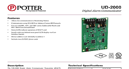
Features allows for communication to Monitoring Station using SIa DCS or ademco Contact ID protocols use with 6000 series and p series addressable panels LeDs indicate operation of DaCT card with ease behind main panel LCD display via User Interface Device address is set by dipswitches located on DaCT card materials including 4 pin connector and screw are supplied DaCT card UUKL Listed with Smoke Control UD 1000 Digital alarm Communicator Transmitter DaCT for up to two 2 phone lines for communication to a station The UD 1000 communicates using the SIa or ademco Contact ID protocols When enabled the DaCT monitors each phone line or voltage and has the to seize the line and connect with a remote receiver Once the is complete the DaCT will hang up DaCT is provided with an RJ 11 jack for each phone line and a to RJ 33 cord In order for the DaCT to work properly it must installed on a plain old telephone service pOTS line or equivalent by the authority having jurisdiction The DaCT must be before any other equipment to ensure it can seize the phone lines are high voltage and should be run in a separate conduit other circuits The wire conductors connecting the DaCT to the system should be 26 aWg or larger Specifications Voltage Current Current UD 1000s per panel Tempuratures Humidity Range Options Weight 6 1 5 8 49 32 120 93 30 86 FaCp Behind keypad lbs page 1 OF 2 REV B 12 18Potter Electric Signal Company LLC St Louis MO Tech Support 866 956 1211 Customer Service 866 572 3005 www pottersignal comUD 1000Digital Alarm Communicatorfirealarmresources com DACT Installation on 1 DACT Installation on 2 DACT in guides under main board 593 32A Connector pFC 6075 board DACT in guides under main board 593 32A in accordance with compatible fire alarm control panel manual E 1 1 D 1 1 UD 1000 DaCT is connected to the control panel using the provided four wire cable connection p N 5210514 between p4 and UD 1000 p1 The is power limited and supervised power system down Slide the UD 1000 into the card guides located under the User Interface bracket Secure the UD 1000 to the User Interface bracket using the provided 6 32x3 8 screw the provided four wire conductor jumper between UD 1000 p1 and p4 B 1 1 Connector pFC 6800 board page 2 OF 2 REV B 12 18Potter Electric Signal Company LLC St Louis MO Tech Support 866 956 1211 Customer Service 866 572 3005 www pottersignal comUD 1000Digital Alarm Communicatorfirealarmresources com