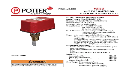
Potter VSR-S Series Waterflow Alarm Switch for Small Pipe

File Preview
Click below to download for free
Click below to download for free
File Data
| Name | potter-vsr-s-series-waterflow-alarm-switch-for-small-pipe-6421509783.pdf |
|---|---|
| Type | |
| Size | 1.49 MB |
| Downloads |
Text Preview
Features Assembled in USA 0 90 second field replaceable time delay retard Easy to read retard time delay adjustment knob Fits 1 to 2 CPVC copper brass or iron pipe Comes with all necessary paddles Two SPDT form C contacts Weatherproof Easy to read wire terminal designations 5 year warranty switches that are monitoring wet pipe sprinkler systems not be used as the sole initiating device to discharge AFFF or chemical suppression systems Waterflow switches used this application may result in unintended discharges caused by trapped air or short retard times Required for Specifications Pressure This document contains important information on the installation and operation of the VSR S waterflow switches Please read all instructions before beginning installation A copy of this document is required by NFPA 72 to be maintained on site Model VSR S is a vane type waterflow switch for use on wet systems that use 1 25mm 1 32mm 1 38mm or 2 pipe size The unit may also be used as a sectional waterflow on large systems unit contains two single pole double throw snap action switches an adjustable instantly recycling pneumatic retard The switches actuated when a flow of 10 gallons per minute 38 LPM or more downstream of the device The flow condition must exist for a of time necessary to overcome the selected retard period VSR S switches and retard device are enclosed in a general die cast housing The cover is held in place with two tamper screws which require a special key for removal A field cover tamper switch is available as an option which may used to indicate unauthorized removal of the cover See bulletin 5401103 for installation instructions of this switch PSI 20,68 BAR UL GPM 38 LPM ensure minimum flow of 10 gpm a minimum pressure is at all sprinklers with a k factor of 3 or less 10 PSI 12 PSI FPS 5,5 m s red powdercoat finish sets of SPDT Form C Amps at 125 250VAC Amps at 30VDC Resistive mAmps min at 24VDC 1 2 conduit connections provided Individual switch suitable for dissimilar voltages plastic copper schedule 40 iron pipe and unlisted riser approved by Potter pipe sizes 1 1 1 and 2 12 paddles are furnished with each unit one for each pipe of threaded and sweat TEE one for 1 CPVC one for 1 Central one for 1 threaded Nibco CPVC and one for threaded Japan NEMA 4 IP65 Rated Enclosure suitable for indoor or use with factory installed gasket and die cast housing when with appropriate conduit fitting Temperature Range 40 120 4.5 49 UL Sprinkler or two family dwelling occupancy up to four stories Fire Alarm Code subject to change without notice must be performed by qualified personnel in accordance with all national and local codes and hazard Disconnect power source before servicing injury or death could result of explosion Not for use in hazardous locations Serious or death could result Surge Entrances Ratings Use page 1 OF 6 Type Waterflow Alarm Switch With Retard5401206 REV H 05 19Potter Electric Signal Company LLC St Louis MO Phone 800 325 3936 www pottersignal comfirealarmresources com devices may be mounted in horizontal or vertical pipe On horizontal pipe they should be installed on the top side of the pipe where they will accessible The units should not be installed within 6 15cm of a fitting which changes the direction of the waterflow or within 24 of a valve or Select the proper paddle for the pipe size and type of TEE used see Fig 2 for instructions on changing paddle The unit has a 1 NPT bushing for into a TEE See Fig 1 for proper TEE size type and installation Use no more than three wraps of teflon tape the device into the TEE fitting as shown in Fig 1 Care must be taken to properly orient the device for the direction of waterflow vane must not rub the inside of the TEE or bind in any way The stem should move freely when operated by hand device can also be used in copper or plastic pipe installations with the proper adapters so that the specified TEE fitting may be installed on the pipe Do not leave cover off for an extended period of time not trim the paddle Failure to follow these instructions may prevent the device from operating and will void the warranty Do not obstruct or otherwise the trip stem of the flow switch from moving when water flows as this could damage the flow switch and prevent an alarm If an alarm is not a Flowswitch Bypass Switch should be used refer to Potter data sheet 5401554 or a qualified technician should disable the alarm system 1 COVER TAMPER SWITCH Adjustment delay can be adjusted by rotating the retard adjustment knob from to the max setting 60 90 seconds The time delay should be set at minimum required to prevent false alarms Selection 2 OF FLOW 737 31 SO ARROW ON POINTS IN OF WATERFLOW NPT THREADED ON ALL SIZES OF THE TEE MAY BE OR SWEAT PIPE OF 802 30A are 12 paddles furnished with each unit One for each size of sweat or plastic TEE as described in Fig 3 These paddles raised lettering that shows the pipe size and type of TEE that are to be used with The proper paddle must be used The paddle be properly attached see drawing and the screw that holds the must be securely tightened Do not trim the paddle For National Fire Products risers use paddle marked SWEAT corresponding size riser PAGE 2 OF 6 REV H 05 19Potter Electric Signal Company LLC St Louis MO Phone 800 325 3936 www pottersignal comVSR SVane Type Waterflow Alarm Switch With Retardfirealarmresources com Specifications the fitting into the TEE fitting as shown in Fig 3 3 Tamper Switch Wiring 4 with cover in place 1 11 16 APPROX 735 33 depth to the inside bottom of the TEE should have the following Depth Requirement Size x 1 x 1 1 16 3 4 7 16 1 4 x 1 1 4 x 1 7 16 7 16 1 2 x 1 1 2 x 1 11 16 x 2 x 1 3 16 1 4 3 4 only factory TEE with a 1 NPT bull Threaded bushings bushings mechanical TEE and weld o lets are not unless they comply with the dimensions listed in the chart Fig 3 and have been factory approved by Potter Apply teflon to the 1 NPT fitting Do not use more than three wraps of tape Do not use any other type of sealant 8810018 2 Terminal Connections Plate Terminal 5 uninsulated section of a single conductor should not be looped the terminal and serve as two separate connections The wire be severed thereby providing supervision of the connection in event that the wire become dislodged from under the terminal to sever the wire may render the device inoperable risking property damage and loss of life not strip wire beyond 3 8 of length or expose an uninsulated beyond the edge of the terminal block When using wire capture all strands under the clamping plate PAGE 3 OF 6 REV H 05 19Potter Electric Signal Company LLC St Louis MO Phone 800 325 3936 www pottersignal comVSR SVane Type Waterflow Alarm Switch With Retardfirealarmresources com Electrical Connections 6 FROM FROM BELL FROM BREAKER End Of Line Resistor connecting to a UL Listed panel use the panel value for circuit supervision VSR S does not require power to operate Do not connect AC power directly to the terminals as this will damage the switch terminals are for switching power to an indicating appliance such as a bell or strobe Similar to how a light switch is used to switch power to a