Potter Waterflow Alarm Switch for Copper Pipe
File Preview
Click below to download for free
Click below to download for free
File Data
| Name | potter-waterflow-alarm-switch-for-copper-pipe-4956812073.pdf |
|---|---|
| Type | |
| Size | 1.06 MB |
| Downloads |
Text Preview
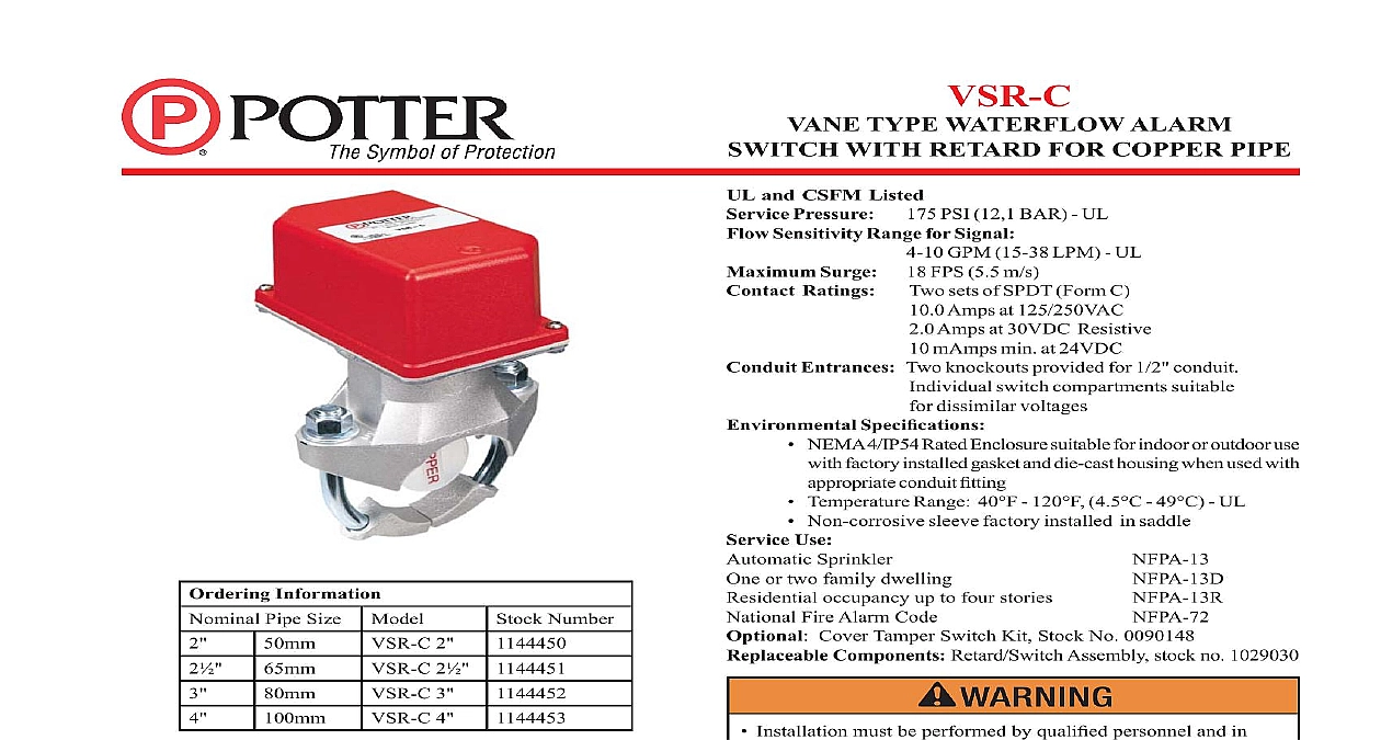
VSR C TYPE WATERFLOW ALARM WITH RETARD FOR COPPER PIPE 4 10 GPM 15 38 LPM UL and CSFM Listed Pressure 175 PSI 12,1 BAR UL Sensitivity Range for Signal Surge 18 FPS 5.5 m s Ratings sets of SPDT Form C Amps at 125 250VAC Amps at 30VDC Resistive mAmps min at 24VDC Entrances Two knockouts provided for 1 2 conduit switch compartments suitable dissimilar voltages Speci cations NEMA 4 IP54 Rated Enclosure suitable for indoor or outdoor use factory installed gasket and die cast housing when used with conduit tting Temperature Range 40 120 4.5 49 UL Non corrosive sleeve factory installed in saddle Use Sprinkler or two family dwelling occupancy up to four stories Fire Alarm Code Cover Tamper Switch Kit Stock No 0090148 Components Retard Switch Assembly stock no 1029030 Installation must be performed by quali ed personnel and in accordance with all national and local codes and ordinances Shock hazard Disconnect power source before servicing Serious injury or death could result Risk of explosion Not for use in hazardous locations Serious injury or death could result Information Pipe Size Model 2 2 3 4 Number Information Model VSR C is a vane type water ow switch for use on wet systems It is UL Listed for use on Type K L and M copper sizes 2 thru 4 50mm 100mm VSR C may also be used as a sectional water ow detector on systems VSR C contains two single pole double throw snap action and an adjustable instantly recycling pneumatic retard The are actuated when a ow of 10 GPM 38 LPM or more occurs of the device The ow condition must exist for a period time necessary to overcome the selected retard period VSR C switches and retard device are enclosed in a general die cast housing The cover is held in place with two tamper screws which require a special key for removal A field cover tamper switch is available as an option which may used to indicate unauthorized removal of the cover See bulletin 5401103 for installation instructions of this switch See Fig 1 devices may be mounted on horizontal or vertical pipe On pipe they should be installed on the top side of the pipe they will be accessible The device should not be installed within 15 cm of a tting which changes the direction of the water ow or 24 60 cm of a valve or drain Do not leave cover off for an extended period of time the system and drill a hole in the pipe using a hole saw in a slow drill see Fig 1 the inside pipe of all growth or other material for a distance equal the pipe diameter on either side of the hole the vane so that it may be inserted into the hole do not bend or it Insert the vane so that the arrow on the saddle points in the of the water ow Install the saddle strap and tighten nuts to required torque see Fig 1 The vane must not rub the of the pipe or bind in any way cations subject to change without notice Electric Signal Company LLC 2081 Craig Road St Louis MO 63146 4161 Phone 800 325 3936 Canada 888 882 1833 www pottersignal com IN USA PAGE 1 OF 3 5401203 REV D 1 COVER TAMPER SWITCH ADJUSTMENT DELAY CAN BE ADJUSTED BY ROTATING THE ADJUSTMENT KNOB FROM 0 TO THE MAX 60 90 SECONDS THE TIME DELAY SHOULD SET AT THE MINIMUM REQUIRED TO PREVENT ALARMS NOT LEAVE COVER OFF FOR PERIOD OF TIME 2 2 ONLY 2 5180162 ADAPTERS AS SHOWN ABOVE 1203 1 OF water activates in one direction only 2 2 3 4 Pipe O D 1146 2A Requirements Size 062 2.0 062 125 2.0 Nuts Torque TYPE WATERFLOW ALARM WITH RETARD FOR COPPER PIPE 2 Switch Terminal Connections Clamping Plate Terminal NUTS ON PIPE SO ON SADDLE IN DIRECTION WATERFLOW PADDLE IN DIRECTION WATERFLOW 3 75MM AND 4 100MM SIZE COLLAR UNDER U BOLT SHOWN I N N I N 923 3 uninsulated section of a single conductor should not looped around the terminal and serve as two separate The wire must be severed thereby providing of the connection in the event that the wire dislodged from under the terminal Failure to sever wire may render the device inoperable risking severe damage and loss of life ow switches that are monitoring wet pipe sprinkler shall not be used as the sole initiating device to AFFF deluge or chemical suppression systems ow switches used for this application may result unintended discharges caused by surges trapped air or retard times 3 Electrical Connections 4 out thin section of cover when wiring switches from one conduit entrance 5 remove knockouts Place screwdriver at edge of knockouts not in the center OR DC HOT AC ZONE FIRE PANEL 1146 3A The Model VSR C has two switches one can be used to a central station proprietary or remote signaling while the other contact is used to operate a local audible visual annunciator For supervised circuits see Terminal Connections and caution note Fig 2 1146 5 1146 4 IN USA 5401203 REV D PAGE 2 OF 3 TYPE WATERFLOW ALARM WITH RETARD FOR COPPER PIPE To prevent accidental water damage all control valves should be shut tight and the system completely drained before water ow detectors are removed or replaced Turn off electrical power to the detector then disconnect wiring Loosen nuts and remove U bolts Gently lift the saddle far enough to get your ngers under it With your ngers roll the vane so it will t through the hole while continuing to lift the water ow detector saddle Lift detector clear of pipe Notice advise the person responsible for testing of the re protection system this system must be tested in accordance with the testing instructions frequency of inspection and testing for the Model VSR C and its protective monitoring system should be in accordance with NFPA Codes and Standards and or the authority having manufacturer recommends quarterly or more frequently provided the inspector test valve that is usually located at the end the most remote branch line should always be used for test purposes there are no provisions for testing the operation of the ow detection on the system application of the VSR C is not recommended advisable minimum ow of 10 GPM 38 LPM is required to activate this device detectors monthly for leaks If leaks are found replace the detector VSR C water ow switch should provide years of trouble free service retard and switch assembly are easily eld replaceable In the unlikely that either component does not perform properly please order retard switch assembly stock number 1029030 There is no required only periodic testing and inspection Dimensions 1203 3 DIA NUT