Cerberus Pyrotronics 3 X3 Air Duct Detector

File Preview
Click below to download for free
Click below to download for free
File Data
| Name | cerberus-pyrotronics-3-x3-air-duct-detector-0658471923.pdf |
|---|---|
| Type | |
| Size | 1.10 MB |
| Downloads |
Text Preview
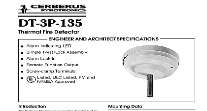
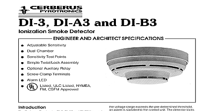
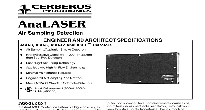
Air Duct Housings AND ARCHITECT SPECIFICATIONS Series IL and Series 3 Ionization or Detectors Optional Relays for Supplementary Operation Optional Control Module for Self contained Series 3 Detectors Only Alarm LED Visible from Front Clear Housing Cover for Quick of Detector Type Listed ULC Listed NYMEA FM CSFM and City of Chicago Approved Cerberus Pyrotronics air duct detector housings are to be used with Cerberus Pyrotronics Series IL and Series 3 ionization or photoelectric detectors for installation directly to heating ventilating and conditioning duct systems they comply with National Protection Association Standard No 90A When with ionization or photoelectric detectors these will signal the presence of hazardous quantities of of combustion or smoke being carried through duct system Air duct detectors are not intended to be for open area detection duct housings can be equipped with optional relays relays are utilized to operate any supplementary when smoke or particles of combustion are Most control equipment including System 3 guaran only one detector per zone is permitted when the operated relay function is critical The connection a remote lamp or a remote relay per detector is allowed not both XL3 control panel assures operation of all detector relays therefore up to 30 detectors per circuit relays for critical functions may be used For the control panel up to 60 detectors per circuit having may be used The connection of a remote lamp or a relay is allowed for each detector but not both duct housings see Ordering Information are Under Laboratories Inc listed Cerberus Pyrotronics air duct housing is uniquely to use the highly sensitive yet stable Series IL and Series 3 detectors sensitivity of Series 3 detectors can be checked in under actual dynamic air flow conditions using a Pyrotronics sensitivity test module The sensitivity Series IL detectors can be checked in place under dynamic conditions at the XL3 control panel MXL panel or IXL respectively or may be printed by on the optional printer detector unit employs a cross sectional sampling of operation Inlet sampling tubes are available in lengths see table on reverse side Outlet sampling are one common length A continuous cross sample of air moving through the duct is taken averages the effects of laminar flow stratification or effect phenomena occurring in the duct that could combustion product or smoke especially in large from reaching a spot type detector addition the unique design of the Cerberus Pyrotronics chamber insures uniform sensitivity in air veloci ranging from a low of 300 feet per minute to as high 4000 feet per minute NUMBER handling equipment shall be shut down by a signal the fire detection system control equipment When air duct housing incorporates the optional relay the down of air handling devices may be accomplished a signal directly from the detector air duct housing shall be available with a self con power supply so that it can function as a stand unit if desired The self contained stand alone unit power and supervise two satellite units air duct housing shall utilize a plug in detector head in the air sampling chamber The detector shall be ionization or photoelectric There shall be provisions check the detector sensitivity in place under actual air conditions air duct housing shall be mounted directly outside of air duct by means of four bolts supplied A template be provided for making necessary cut outs and holes instructions shall be supplied with the unit air duct housing shall be a Cerberus Pyrotronics See listing on back page and shall be Laboratories Inc Listed specifically for use air handling systems to Architect When building codes regulate the of detectors within ventilating systems make sure the number and locations of detectors is in accor with the code regulations Series and the PEC 3 detectors are obsolete of 1 1 92 The IL Series are direct replacement for ID 60 and Series and the PE 3 for the PEC 3 inlet sampling tube length is determined by the width the air duct being protected The inlet tube nearest to greater than the duct width should be used see table inlet tube can then be trimmed at the job site to the width of the duct The outlet sampling tube for all irrespective of width has a fixed length of approxi 3 inches 7.5 cm and is supplied with the duct the use of a remote relay is required a relay module for conventional systems or DA X3SR for MXL or IXL systems is used to replace the existing strip in the air duct housing wiring compartment installation diagram Tube Selection Table Width to 1 21 cm to 51 cm to 3 51 cm to 97.5 cm to 6 97.5 cm to 187.5 cm to 9 187.5 cm to 292.5 cm than 9 292.5 cm of the detector is easily accomplished by the of the Series 3 X3 duct housing sampling cham cover The detector which plugs into the housing is removed for cleaning by a trained technician that is necessary for the installation of the air duct detect is the cutting of three small holes for the sampling tube template included and the drilling of four holes mounting the air duct housing The unit is then easily in place and connection made to the existing wires terminals if optional accessories are utilized and Architect Specifications air duct housing for the fire detection system shall be Cerberus Pyrotronics Series 3 X3 air duct housing Tube Model No Pyrotronics air duct housing shall incorporate the use of one of the detectors IL Photelectric IL Ionization IL Ionization Altitude 3000 8000 ft 3 Ionization 3 Ionization Altitude 3000 8000 ft 3 Photoelectric ID 60 Ionization ID 60 Ionization Altitude 3000 8000 ft ID 60 Photoelectric ILP 1 ILI 1B ILI 1BH DI B3 DI B3H PE 3 ID 60IB ID 60IBH ID 60P air duct housing unit shall be designed for detection of products and or smoke in air conditioning and system ducts in compliance with NFPA Stan 90A The assembly shall consist of a housing to sampling tubes which extend into and the duct of the ventilation system the fans are operating a continuous cross sectional of air from the duct shall flow through the se ionization or photoelectric detector after which the air shall be returned to the duct Diagram Wiring Wiring for Self Contained Unit and Satellite Wiring for System 3 SXL PXL Wiring for MXL and ICon 1 IXL Connections for INS 2 IXL Use Information Weight Kg No 3 air duct housing with cover for the Series 3 ILI Series and ID 60I ionization detectors 3 3X air duct housing with cover for the ILP 1 and PE3 detectors relay board for use with AD 3I or AD 3ILP with DI 3 or PE 3 detectors relay board for use with AD 3I or AD 3ILP with IL or ID60 detectors 3 air duct housing with power supply for self contained unit and with cover for Series 3 ionization detectors 3 air duct housing with power supply for self contained unit and with cover for Series 3 photoelectric detectors Tube for ducts 9 to 1 Tube for ducts 1 to 3 Tube for ducts 3 to 6 Tube for ducts 6 to 9 Sampling Tubes greater than consult Cerberus Pyrotronics Switch 3 ionization detector 3 photoelectric detector ILI ionization detector 3 ionization detector for altitudes of 3000 8000 ft 45 9 45 45 45 45 45 45 45 45 45 45 45 ILI ionization detector for altitudes of 3000 8000 ft ILP photoelectric detector test module for Series 3 ionization detector test module for Series 3 photoelectric detector test module for PEZ 3 test module cable ass