Cerberus Pyrotronics CP-35 System 3 Control Panel 3060

File Preview
Click below to download for free
Click below to download for free
File Data
| Name | cerberus-pyrotronics-cp-35-system-3-control-panel-3060-8739516402.pdf |
|---|---|
| Type | |
| Size | 838.27 KB |
| Downloads |
Text Preview
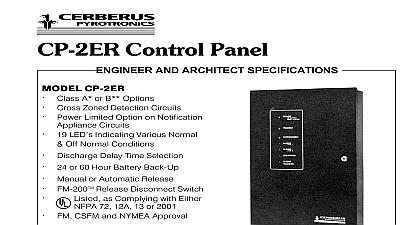
ENGINEER AND ARCHITECT SPECIFICATIONS 3 Control Panel Basic Two Zone System Expandable Double Supervision Ground Detection Supervised Alarm Relay Coil Listed ULC Listed FM CSFM and NYMEA Approved Cerberus Pyrotronics control panel model CP 35 is the control unit for the System 3 universal alarm control is of solid state circuitry and is designed for use in institutional industrial and life safety applica The unit is Underwriters Laboratories Inc listed and approved for service in accordance with NFPA 72 The is also UL listed for waterflow alarm and supple modules included in the system model CP 35 and its associated PS 35 Power Supply circuitry for two supervised detector circuits wired either Class A or Class B Styles D or B respectively CP 35 control panel accommodates any of Cerberus conventional low voltage detectors manual or contact type input devices The CP 35 also one supervised audible signal circuit utilizing 120 VAC or 24 VDC audible devices The audible circuit can be wired in either a Class A or B Styles Z Y respectively configured when using 24 VDC audibles 120 VAC audibles are used the circuit can only be wired a Class B Style W circuit two initiating zones within the CP 35 are power limited NFPA 70 With the addition of a PLM 35 module the circuit also becomes a power limited circuit visual system indicators are mounted on the face of CP 35 a green Power On LED a red Alarm LED a Trouble LED and a yellow Ground Fault LED To the two detector circuits a red Zone Alarm LED a yellow Zone Trouble LED are supplied for each An additional yellow Audible Signal Circuit Trouble is also provided momentary contact switches are mounted on the CP one serving as a combination Test while the other permits Silence A fixed position Silence switch and an internal signal sounding device is provided A remotely Alarm and Trouble Annunciator RTA 38 is op combination of a Model CP 35 with a PS 35 operates a three wire 120 240 VAC 50 60 Hz supply with neutral incorporating double supervision power may be supplied with option standby The green Power LED is illuminated to show that is normal Each input power line is separately fused the power supply of the main AC operating power or secondary AC power is signaled by the system audible and visual trouble LED Restoration of power returns the to normal condition When standby battery is loss of main power results in an audible and trouble signal and the batteries provide power to the NUMBER system power supply furnishes power for detector and audible signal circuits The detector circuits be the two zones incorporated in the CP 35 control any mix of additional compatible zones signal circuits other fire monitoring circuits In addition an output rated 24 VDC 1.5A is provided on terminals 5 and 6 of the PS for powering modules internally housed and wired within control unit enclosure control panel alarm section circuitry responds to any module alarm input signal either from the on board or separate zone modules The alarm condition is In within the control panel and is cleared only by of the control panel switch An alarm is indicated by Change of state of the two SPDT alarm relay con of the panel visual indicator Energizing of both the silenceable and non alarm outputs High going current limited alarm signal Alarm signal output to the remote alarm and silence Operation of the momentary Silence causes both the silenceable alarm output to and the visual alarm indicator to flash Alarm operation of the Silence switch following a alarm condition the system visual indicator oper in a flashing mode A subsequent alarm input from a zone will cause a renewed high going signal on silenceable alarm output terminal causing the associ or connected audible devices to be energized again operation may be repeated for up to ten 10 subse alarm conditions alarm input signals from two or more zone are considered to be but a single alarm input Operation of the panel mounted alarm silence when no alarm is present has no effect Operation the key operated momentary remote alarm station switch will cause a system trouble condition when panel is not in an alarm condition trouble condition in CP 35 will be caused by any of the An open initiating device circuit or initiating device of place An open in the municipal tie circuit An open or short on a notification appliance circuit Removal of a supervised system module of main power and or secondary power if with additional backup Any ground fault within the system or its wiring Auxiliary power output fuse open or missing see momentary reset switch not in its fully closed Failure of the 12VDC logic power supply Alarm relay coil open of 120 VAC trouble phase input supply Key operated remote alarm station silence switch in position when system is not in alarm Battery charger transfer module fault condition trouble conditions are annunciated by the following CP 35 LED illuminates CP 35 built in trouble buzzer sounds High going current limited trouble output Term 43 is relay SPDT contacts changes state output to RTA 38 Term 22 26 is energized control panel audible trouble buzzer may be silenced the control panel trouble silence switch or the remote silence station switch when used Trouble ringback this buzzer is provided to indicate that either the control trouble silence switch or the remote trouble station silence switch is in the off normal or silence when no panel trouble condition is present use of the Cerberus Pyrotronics control panel model permits expansion of system capability to incorpo additional functions over and above the two zone circuits and visual and audible annunciating provided with the basic panel The CP 35 will a combination of the following options Multiple alarm priorities Master Code Municipal tie with disconnect light and switch Remote station connection with the disconnect light switch limit cut out with indicator Supplementary relays Battery standby Remote alarm and Trouble silence Non fire monitoring Reconfirmation Halon release FM 200 Multiple audible circuits Pre action deluge sprinkler control and Architect Specifications and Architect Specifications control panel for the alarm system shall be Cerberus model CP 35 It shall be listed by Underwriters Inc panel shall provide power and necessary components the operation of the basic two zones of supervised circuits and one supervised audible signal circuit 24 VDC devices The detector circuit shall accom ionization photoelectric flame or thermal detec as well as shorting type contact devices intermixed as on the same zone model CP 35 with a PS 35 shall operate from a three 120 240 VAC 50 60 Hz supply Each input shall be fused within the panel It shall include LEDs for power alarm and trouble as well as LED indicators zone alarm zone trouble and audible signal circuit contact switches shall be provided for Test and Silence which shall silence the trouble signal sounding device Alarm receipt shall trouble control panel shall be capable of powering early detectors and audible signal circuits Additional and visual signaling for this capability shall be by Cerberus Pyrotronics modules and as are necessary Interconnection of these to the CP 35 shall be by ten plug and harness which shall provide system power supervision functions and such other circuitry as is for an operable system control panel shall have two 2 sets of normally open normally closed alarm operated relay contacts and 1 set of normally open and normally closed trouble relay contacts All contacts shall be rated at 120 VDC 3 Amp The alarm relay coil shall be super In addition the panel shall have built in ground as well as plug in connectors for emergency It shall be arranged so that alarm signal annuncia shall take precedence over a trouble signal Terminals be provided so that the trouble indi