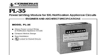
Cerberus Pyrotronics PLM-35 Power Limiting Module 3182

File Preview
Click below to download for free
Click below to download for free
File Data
| Name | cerberus-pyrotronics-plm-35-power-limiting-module-3182-4681597023.pdf |
|---|---|
| Type | |
| Size | 943.66 KB |
| Downloads |
Text Preview
PLM 35 Limiting Module for All Pyrotronics Control Panels AND ARCHITECT SPECIFICATIONS PLM 35 PLM 35 Allows Power Limited Wiring Notification Appliance Circuits Compact Module Design Easy Installation Listed Pyrotronics Power Limiting Module PLM 35 the use of power limited fire protective signaling conductors on 24 VDC notification appliance circuits benefit of installing a PLM 35 module is that the 24 VDC appliance circuits and alarm initiating circuits be installed in the same raceway or enclosure and installations using the PLM 35 meet National Code power limiting requirements The PLM 35 can used in all Cerberus Pyrotronics control panels for their appliance circuits PLM 35 converts the systems 24 VDC electrical non limited circuit to a power limited circuit The modules energy circuitry contains a non replaceable current device The power limiting module is to be con in series with the electrical non power limited source as shown in the connection diagram The may be used with either Style Z Class A or Style W B wiring Specifications conversion of a non power limited 24 VDC notification circuits to a power limited circuit shall be made the use of a Cerberus Pyrotronics Model PLM 35 unit shall be UL listed The unit shall be connected in with the electrical non power limited energy source shall contain a non replaceable overcurrent device power limiting device shall be installed inside the fire system panel The power limited module shall the option of using either Style Z Class A or Style Class B circuits Information Number Power Limiting to Installation Instruction P N 315 093495 NUMBER Diagram STYLE W CLASS B terminal 1 of PL 35 the following terminal 35 terminal 3 MX 316 TB1 2 3 4 terminal 3 4 7 8 11 12 or 15 16 TB2 terminal 2 or 3 terminal 22 or 24 The supervisory line may be wired to the control panel or may be thru PLM 35 to the panel STYLE Z CLASS A negative supervisory lines must be separately fused Connect to the PLM 35 terminals as follows Circuit Circuit Circuit Circuit 3 7 3 4 3 7 11 or 15 4 8 12 or 16 1 1 1 1 1 1 Pyrotronics Ridgedale Avenue Knolls NJ 07927 201 267 1300 201 397 7008 in U S A Pyrotronics East Pearce Street Hill Ontario 1B7 CN 905 764 8384 905 731 9182 1996 Issue


