Siemens 1HU Black Red Backboxes and 2HU Black Red Backboxes, Installation Instructions

File Preview
Click below to download for free
Click below to download for free
File Data
| Name | siemens-1hu-black-red-backboxes-and-2hu-black-red-backboxes-installation-instructions-8742935601.pdf |
|---|---|
| Type | |
| Size | 716.86 KB |
| Downloads |
Text Preview
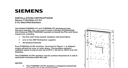
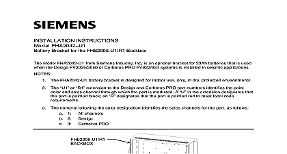
Installation Instructions FHB2001 U1 R1 and FHB2002 U1 R1 Black Red Backboxes and 2HU Black Red Backboxes Model FHB2001 U1 R1 is designed for use with the FT Series display terminals FHB2002 U1 R1 is designed to house system modules power supplies or 300W and batteries Each backbox is shipped empty and without the inner outer doors as shown in Figure 1 and FHB2002 U1 R1 backboxes are for indoor use only in dry environ FHB2001 U1 and FHB2002 U1 backboxes are black the FHB2001 R1 and backboxes are red FHB2001 U1 and FHB2001 R1 are identical in all respects and for the remainder of this document will be referred to as the FHB2002 U1 and FHB2002 R1 are identical in all other respects and for the of this document will be referred to as the FHB2002 BACKBOX NPT 1 1 4 TYP 1 1 4 TYP 2.0 TYP 1 1 4 TYP 1 1 4 TYP 3 1 2 TYP 5.0 TYP ARE DOUBLE 3 4 1.0 NPT SIZES OF 3 PLACES EXCEPT THE 3 AT THE BOTTOM 1 Backbox with Knockout Locations NPT B Inc Inc Inc Industry Inc Inc TTTTTececececechnologies Di Di Di Division Di BACKBOX 1 1 2 TYP 3 1 2 TYP 3 1 2 TYP 3 1 2 TYP 1 1 2 TYP 1 1 2 TYP 1 1 2 TYP 2 1 2 TYP 6 1 8 TYP 2 1 2 TYP 7 1 2 TYP 2 1 2 TYP NPT KNOCKOUTS ARE DOUBLE 3 4 1.0 NPT SIZES OF 9 PLACES EXCEPT THE 2 AT THE BOTTOM 2 Backbox with Knockout Locations to installation consider the following FHB2001 and FHB2002 backboxes are mounted on a flat surface with four user bolts that are a minimum of 3 8 inch in diameter FHB2001 backboxes contain space in the bottom to mount a set of BT 33 7.5AH batteries FHB2002 contain enough space in the bottom to mount a set of BTX 1 33AH when only the upper inner door is used When both upper and lower inner are used in FHB2002 backboxes batteries larger than 18AH BP61 require an battery box Mounting height for visual and manual access to the Person Machine PMI displayed in an opening of the outer door Weight and size of the enclosure enclosure installation must meet the requirements of NFPA 72 the Having Jurisdiction and local codes of the outer door opening all doors are hinged left a clean dry shock and vibration free surface the backbox clear of obstructions so that the front door opens and the controls and indicators are easily accessible Mark the locations of the two upper mounting bolts of the backbox on the Refer to Figure 3 for the FHB2001 and Figure 4 for the FHB2002 There are two key shaped cutouts on the top of the backbox Make sure the end with the key shaped cutouts is on top when installing the backbox Refer to Figure 3 and 4 Drill the two holes located in the previous step and screw in the top bolts a small gap between the wall and each top bolt Refer to Figure 3 the FHB2001 and Figure 4 for the FHB2002 the backbox over the two top bolts and allow it to slide down over the Mark drill and install the two bottom bolts in the backbox all four bolts securely against the back wall of the backbox the backbox Industry Inc Technologies Division STRAP LOOSE END BE MOUNTED THE OUTER BACKBOX 3 Holes for the FHB2001 FOR HOLES FHB2002 B BACKBOX STRAP LOOSE END BE MOUNTED THE OUTER LUG LUG IS FOR THE INPUT ADDITIONAL 2 HOLES TO THE BOX THE WALL FOR APPLICATION A B E F ARE USED TO MOUNT THE 170W POWER SUPPLY A B C D ARE USED TO MOUNT THE 300W POWER SUPPLY GROUND LUG BEFORE MOUNTING THE POWER SUPPLY INSTALLING THE POWER SUPPLY BE SURE TO REINSTALL GROUND LUG 4 Holes for the FHB2002 Industry Inc Technologies Division compliance with NEC Article 760 all power limited fire protective signaling must be separated a minimum of 1 4 inch from all of the following wiring within a control panel light 1 or non power limited fire protective signaling conductors meet these requirements the following guidelines must be observed when modules and wiring to this control panel installing power limited field wiring the installer must comply with NEC article which states fire alarm power limited circuits are installed using Types FPL FPLR FPLP or substitute cable provided these power limited cable conductors extending the jacket are separated by a minimum of 0.25 in 6.35 mm or by a noncon sleeve or nonconductive barrier from all other conductors energy limited cable or equivalent is not used within the FHB2001 enclosure the following guidelines do not apply In that case be sure to follow standard practices Entering Enclosure to Figure 1 and Figure 2 in the FC2025 FC2050 FT2050 Fire Alarm Control Installation Instructions Document ID A6V10337045 and the FC922 FC924 Fire Alarm Control Panel Installation Instructions Document ID A6V10356958 Limited Wiring entering the enclosure from the bottom and right side of the backbox is non power limited wiring Wiring must be in the shortest route and must overlap any other wiring Limited Wiring entering the enclosure from the left side of the backbox is considered power Wiring must be in the shortest route and must not overlap any other wiring the existing lances in the backbox to dress the wires as needed to maintain of power limited and non power limited wiring Wiring primary mains input must have a separate or dedicated circuit breaker Wire in with local codes and NEC 760 the knockouts in the backbox for the entry of field wiring all field wiring into the backbox Do not dress the wiring until the of all the equipment is known the wiring from the external power source to the approximate of the power supply FHB2001 backboxes can be used with the FHD2001 outer door and the inner door FHB2002 backboxes can be used with FHD2002 or FHD2003 outer doors inner doors and FHD2005 solid inner doors FHB2002 backboxes when both upper and lower inner doors are used FHD2004 batteries larger than 18AH require an external battery box x 3 7 8 x 15 x 5 7 8 x 27 5 8 Industry Inc Technologies Division Park NJ Canada Ltd North Service Road East Ontario 0H6 Canada A5Q00053431 ID A6V10335922 en b