Siemens AIC Audio Input Card, Installation Instructions

File Preview
Click below to download for free
Click below to download for free
File Data
| Name | siemens-aic-audio-input-card-installation-instructions-8043612795.pdf |
|---|---|
| Type | |
| Size | 733.48 KB |
| Downloads |
Text Preview
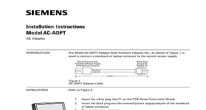
s Instructions AIC Input Card 500 035300 S24235 B2 A2 Siemens Model AIC Audio Input Card is a that provides 2 external isolated analog audio to the voice system External audio sources recorder CD player tuner PBX interface for paging through the telephone system other input can be configured independently for usages via the Zeus tool Each input can controlled automatically via system logic on its individual configuration or by using the voice control panel The input can be adjusted via the Zeus tool or manually push buttons at the AIC front panel During the power up condition each input is shut off features are as follows 2 independent analog audio inputs separately transformer isolated separately supervised for Loss of Signal Separate input level adaptation for each input Separate level indicator for level adaptation for input at front panel Separate analog digital converter Firmware update via PMI Control data via CAN protocol Digital audio connection via ASI protocol Edition 3 315 035300 3 1 Front Panel s AIC contains two audio input circuits Each input can be adapted to input levels between 15dBu to 12dBu The adapted input is indicated at the front panel via 3 LEDs The inputs are separately isolated and supervised for presence of audio input signal This the use of independent audio signal sources with independent ground AIC provides sampling rates from 48kHz 24kHz 12kHz and resolution 16bit and 8bit separately for each input Reduction of sampling rate and is only needed in applications with distributed system architecture D NET external digital bus to connect nodes is needed Centralized systems with only one single control panel no D NET will always have maximum audio quality 48kHz sampling rate 16 bit resolution Each AIC occupies one card slot in the CC 5 or CC 2 cardcage The AIC indicates status by diagnostic LEDs RESET switch diagnostic LEDs to indicate the operation of the card pairs of switches to separately adapt the two audio input levels pair of three LEDs to indicate the input level adaptation for each input CAN address switch reset switch is located on the top of the front panel Pushing the reset re initializes the AIC operation and Indicators front panel of the AIC contains the following as shown in Figure 1 Edition 3 315 035300 3 OF diagnostic LEDs follow the reset switch Their function is defined as NORMAL ILLUMINATED IN DEVIANT STATE that power for the AIC applied to the card on AIC PSC 12C backplane or wiring FAIL a general trouble at on AIC FAIL that the CAN has terminated the card enters degrade on AIC DAC NET backplane or other Cards FAIL on AIC DAC NET backplane or other ASI Active Trouble Active Trouble that the ASI has stopped the card enters degrade that audio input 1 is that the AIC has a trouble on input 1 of signal that audio input 2 is that the AIC has a trouble on input 2 of signal 1 activated 1 no signal 2 activated 2 no signal LEDs and 2 switches for each audio input follow the diagnostic LEDs and function is defined as follows OF LED ILLUMINATED only one at a time that the input level is too high and signal will be clipped the DOWN switch to the input level that the input level is correct action that the input level is too low the UP switch to the input level WHEN SWITCH IS PRESSED LESS THAN 2 SECONDS WHEN SWITCH IS PRESSED LONGER THAN 2 SECONDS input level will be adapted with a pre amplification of 1 dB input level will be adapted with a pre amplification of 1 dB input level will be adapted with a pre amplification in steps of 1 dB half a second input level will be adapted with a pre amplification in steps of 1 dB half a second Edition 3 315 035300 3 two position switch at the bottom of the front panel is used to set the CAN address of the AIC Network Address Switch Set the two digit CAN network address for AIC using the two position switch located near the bottom of the front Refer to figure 1 for the location of the switch The address selected the front panel of the AIC must be the same as the address selected in the programming tool To increment each digit of the address press the above the desired digit to decrement each digit press the button the desired digit Allowable addresses are from 01 to 99 leading zeros be used ELECTRICAL POWER prior to working on equipment field wiring of the AIC is connected to the terminal blocks of the CC 5 CC card cage slot in which it is installed The screw terminals can one 12 24 AWG 2,5mm2 or two 16 24 AWG 1,5mm2 connect external wiring Lift the white cover on the terminal block the screw of the terminal by turning it counterclockwise the wire into the side of the terminal block the screw of the terminal block by turning it clockwise Connections No EOLR required 24 AWG 1,5mm2 min 12 AWG 2,5mm2 max Use twisted pair or twisted pair All wiring must be within 20 feet 6,5m and in rigid conduit Audio activation inputs must be to dry contacts only 2 AIC Terminal Connections Edition 3 315 035300 3 AIC plugs perpendicularly into one slot in the CC 5 card cage via two 96 DIN connectors and can occupy any slot in the card cage 3 Installing the AIC the AIC card into the card guides rightside up lettering on the front is legible Slide the card in until the card edge connectors contact the on the motherboard Verify that the DIN connectors of the card the card cage aligned properly The card can only plug in one direction to card cage if it does not align DO NOT FORCE the card thumbs on the front panel adjacent to the captive screws and gently even pressure on the card until the connectors seat in the receptacles the motherboard with the captive screws up the system and verify that the AIC power LED turns ON Edition 3 315 035300 3 RATINGS Power Back Plane Current Screw Terminal Current Standby Current mA mA mA Back Plane Current mA 50mA per Active Channel Ratings AIC Input nominal Input Range max Control Range 1mW 0.775VRMS 600 symmetric to 15dBu 27 dB to 4.34VRMS to 12,3Vpp CE applications in Cerberus E100 systems refer to Instruction A24205 A334 B844 English or A24205 A334 A844 German Siemens Geb GmbH Co oHG 2003 Siemens Building Technologies Inc Florham Park New Jersey 07932 Siemens Building Technologies Ltd Brampton Ontario L6T 5E4 CN by Siemens GmbH Co oHG M subject to availability of technical modifications reserved No A24205 A334 B838 Edition 3 315 035300 3 in the Federal Republic of Germany environmental chlorine free paper