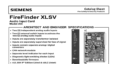
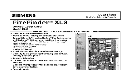
Siemens ALCC (for FireFinder) Audio Level Conversion Card, Data Sheet

File Preview
Click below to download for free
Click below to download for free
File Data
| Name | siemens-alcc-for-firefinder-audio-level-conversion-card-data-sheet-1864792530.pdf |
|---|---|
| Type | |
| Size | 895.29 KB |
| Downloads |
Text Preview
Catalog XLSV Level Conversion Card ALCC Converts speaker level audio at 70VRMS from Model ZAC 30 or FireFinder XLSV ZAC 40 amplifiers to line level audio Supports input from two 2 audio sources with prioritization Supports Class A or Class B wiring 63 Model ALCCs supported on an audio riser Single channel output at 0.775 VRMS output adjustment capability for each channel Audio path supervision for both channels Diagnostic LEDs built in UL 864 9th Edition Listed and ULC Listed Overview Audio Level Conversion Card Model ALCC converts audio at 70VRMS from the MXLV Model amplifier or the FireFinder XLSV Model ZAC 40 to line level audio Audio can be provided the MXLV and FireFinder XLSV systems by Model ALCC in a remote FireFinder XLSV system line level audio output of Model ALCC can then be into the Audio Input Card Model AIC of the FireFinder XLSV system ALCC provides the capability of conducting a page across multiple remote FireFinder nodes with each audio riser holding a maximum of nodes The emergency page originates at a FireFinder or MXLV global paging station where it is broadcast 70VRMS over an audio riser by a Model ZAC 40 XLSV or Model ZAC 30 MXLV amplifier A remote FireFinder XLS node contains one 1 ALCC which steps the incoming speaker level down to line level audio that is compatible with the audio input 0.775VRMS independently adjustable to Industry Inc Technologies Division View View AIC digitizes the audio which is subsequently by a Model DAC NET to local amplifier s for over the local speaker zones ALCC is capable of supporting two 2 global paging since Model ALCC incorporates 2 two audio channels In cases where simultaneous should occur Model ALCC automatically prioritizes signal on the primary channel over the secondary On board audio detection circuitry monitors the risers for incoming audio while supervision circuitry any issues with the audio path via front accessible If necessary supervision circuitry disconnects its from the Model AIC input causing a trouble to be reported to the system ALCC relies on the originating amplifier for of the audio risers and on Model AIC for of the connection to Model ALCC Since Model monitors the presence of signal on its audio input AIC is responsible for reporting audio path faults to FireFinder XLSV system ALCC plugs into one 1 slot in the CC 2 or CC 5 card and can occupy any slot within the card cage XLS 6346 Wiring and Settings For On State For Off State ALCC is powered ALCC is not powered Make certain card is properly plugged Then check for on PSC 12 CC 5 CC 2 presence of audio on the riser absence of audio on the primary check riser wiring if audio is intended presence of audio on the riser of the ALCC is sourced from primary user of the ALCC is sourced from primary user fault is present on the primary channel try cycling the power the card fault is present on the secondary channel try cycling the power the card absence of audio on the secondary check riser wiring if audio is intended output is sourced from the secondary output is sourced from the primary riser audio channel is fully functional audio channel is fully functional Ratings The Back Plane and Screw Terminal currents represent absolute maximum currents consumed by Model ALCC in the operating condition Back Plane and Screw Terminal are only used for loading calculations of the power supply Model ALCC The Standby current represents the current from the 24V battery by Model ALCC in the quiescent mode and is used in the battery size calculation for Ordering Level Conversion Card and Humidity Range are UL 864 9th Edition listed for indoor locations within a temperature range of 49 2 to 32 3 0 2 and at relative humidity of 93 2 at a temperature of 32 2 This marketing catalog sheet is not intended to be used for system design or installation purposes the most up to date information refer to each product installation instructions Industry Inc Technologies Division Safety Fernwood Road Park NJ 07932 973 593 2600 908 547 6877 www SBT Siemens com FIS in U S A Safety Kenview Boulevard Ontario 5E4 Canada 905 799 9937 905 799 9858 2010 sheet dated 7 09 2


