Siemens ASC-2 Audio Supervision Card, Installation Instructions

File Preview
Click below to download for free
Click below to download for free
File Data
| Name | siemens-asc-2-audio-supervision-card-installation-instructions-3817025469.pdf |
|---|---|
| Type | |
| Size | 901.51 KB |
| Downloads |
Text Preview
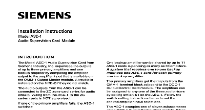
Installation Instructions ASC 2 Supervision Card Model ASC 2 Audio Supervision Card Siemens Industry Inc supervises the of one primary amplifier and one amplifier in an MXLV System The compares the amplifier output to the input from the OMM 1 If they do not a trouble indicates on the MKB 2 The output may be connected in Style or Style Z The audio output can be con to the ZC zone card series the primary amplifier fails the ASC 2 input signal for the failed amplifier to backup amplifier and the backup amplifier output to the channel formerly served by the amplifier card provides the means for multiple cards that supervise many amplifi to share one backup amplifier 1 Module Board primary amplifier gets its input from the terminal block adjacent to the OCC 1 Control Card module The amplifiers be assigned to any one of the three audio by setting switch S2 on the ASC 2 the switch setting instructions in the section to set the desired input selections ASC 2 occupies one of eleven sub of the OCC 1 When installing an card use the CSG M configuration to locate the address of the card Use S1 to set a unique address for the card as described in the INSTALLA section additional information on the Voice refer to the MXLV Manual P N Industry Inc Technologies Division Park NJ 315 092085 11 Building Technologies Ltd Safety Security Products Kenview Boulevard Ontario 5E4 Canada all system power before installation first battery and then AC power up connect the AC first and then the battery Remove the card from its protective bag Do Set the card address on switch S1 using touch the gold edge of the board SW1 SW4 O O O O 8 O O O To open a dipswitch press down on Refer to the CSG M configuration printout for address of the module 1 ADDR O O X 9 O O X O X O 10 O X O O X 11 O X X O O ILLEGAL X O O X O X ILLEGAL X O X X O ILLEGAL X O X ILLEGAL X SWITCH CLOSED OR ON O SWITCH OPEN OR OFF Refer to Figure 2 for the location of S1 Refer to Table 1 for switch settings Set the card address See NOTE below side of the dipswitch marked OPEN close a dipswitch press down on the of the dipswitch opposite the side OPEN open a slide switch push the slide the side opposite the side marked To close a slide switch push the to the side marked ON Switches S1 and S2 and Jumpers J1 and J2 on the ASC 2 2 Set switch S2 for proper supervision of the To set the ASC 2 for 70.7V RMS Refer to No 10 below Place the J1 jumper in the right hand po with the gold plated edge facing up Check that fuse F1 is 2A If the backup amplifier is an EL 410C D the jumper J2 in the upper position the gold plated edge facing up This the backup amplifier input side to the MXLV power supply place J2 in the lower position the data sheet of your amplifier for information Do NOT install the card in its edge connector ALL OMM 1 field wiring is completed checked for shorts opens and other Refer to the Wiring Checkout Chart the card in its protective bag if the is not complete Place the user key from the installation kit in OMM 1 card edge connector for the This prevents the installation of any card type in the ASC 2 slot Two keys prevent reverse installation of the card are factory installed in the OMM 1 edge See Figures 3 and 4 Incorrect settings can cause of the backup amplifier to transfer SWITCH S2 input 1 Riser 2 Riser 3 USED USED X Enable backup amplifier supervision Disable backup amplifier supervision Closed or ON O Open or OFF Check the system wiring plan to be certain amplifier and riser assignments then switch S2 dipswitches SW1 and SW2 following the table above Refer to 2 for the location of switch S2 Close SW5 on switch S2 if this ASC 2 card the backup amplifier If one amplifier is shared by more than ASC 2 card open SW5 of S2 on all cards except the one that the backup amplifier Refer to Figure 2 again note the position of and J2 To set the ASC 2 for 25.2V RMS Refer to No 10 below Place J1 jumper in the left hand position the gold plated edge facing up Check that fuse F1 is 6A 3 the User Key in the OMM 1 4 of the Key for the one backup amplifier is shared by more one ASC 2 connect terminal 3 of the block on the primary ASC 2 to 3 of the terminal blocks of all other cards that share the same backup the system has NO backup amplifier a jumper across terminals 3 and 4 After completing and checking all field wiring the card in its card edge connector components on the board must face the terminal block where the wiring Press the card firmly in place to sure it is seated properly in the edge 2 Use single conductor wire for connections wire length to the decibel dB loss chart in the Application Guide The wire length the amplifier to the ASC 2 the ASC 2 to the ZC series of cards and also includes the wire in the longest zone served by the amplifier level outputs 25.2V RMS 4.0A 100W max RMS 1.4A 100W max amplifier input 1V RMS max to Figures 5 and 6 wiring must comply with and local codes signal is lost in the zone wires due to line Refer to the Speaker Application Guide Then click on Applica Guide in Fire Safety for further information A in load reduces the loss Use the wire size possible for minimum loss CAUTION all times handle all plug in cards with care When inserting or removing card be sure the position of the card is at right angles to the OMM 1 board the plug in card can damage or other components If power limiting is required with a 70.7V use a PLC 4 Refer to the PLC 4 Instructions P N 315 093312 and Figures 5 and 6 for wiring information CHARACTERISTICS wire size 14 AWG twisted pair wire size AWG twisted pair Use unshielded twisted pair for high amplifier connections Use twisted pair for terminals 1 WIRING CHECKOUT CHART BETWEEN CAUSE to 2 through 22 to chassis to 16 to 18 to 20 to 17 to 19 to 20 greater than less than 1 Meg 1 Meg 1 Meg PROBLEM open than EL 410C D in wiring shorted 1.5 ohms open ohms system ohms system open open are the output impedances of EL 410C D power amplifier All wiring must be in with Article 760 of or the local building Minimum wire size 18 AWG Maximum wire size 14 AWG pair pair High level amplifier unshielded pair level amplifier connections shielded twisted pair connections single wire Maximum rating RMS 100W 4.0A each RMS 100W 1.4A each Maximum loop length Refer to 2 and 3 The wire length includes The of the wire from the to the amplifier the of the wire from the to the ZC Series of cards and back and the of the longest speaker served by the amplifier End of Line device 24K P N 140 820405 there is no backup amplifier terminals 3 and 4 If one backup is shared by more one ASC 2 connect all 3s together and leave terminal 4s unconnected Required for power limited to Wiring Specification for MXL IQ and MXLV P N 315 091772 6 or higher for wiring information is located at the last ZC Series or ICP aud