Siemens C-DSC C-DSC-W Dual Sync Control Unit, Installation Instructions and Wiring

File Preview
Click below to download for free
Click below to download for free
File Data
| Name | siemens-c-dsc-c-dsc-w-dual-sync-control-unit-installation-instructions-and-wiring-4361097258.pdf |
|---|---|
| Type | |
| Size | 709.50 KB |
| Downloads |
Text Preview
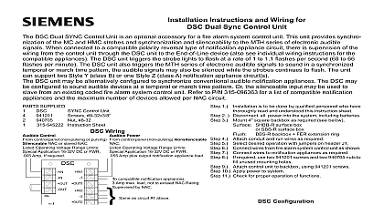
Installation Instructions and Wiring for and C DSC W white Dual Sync Control Unit C DSC red or C DSC W white Dual SYNC Control Unit is an optional accessory for a fire alarm system control unit The of the C DSC and C DSC W is identical and will be referred to as the C DSC throughout the remainder of this document This provides synchronization of the MC and HMC strobes and synchronization and silenceability to the MTH series of electronic audible When connected to a compatible polarity reversal type of notification appliance circuit there is supervision of the wiring from control unit through the C DSC unit to the End of Line device also see individual wiring instructions for the compatible appliances C DSC unit triggers the strobe lights to flash at a rate of 1 to 1.1 flashes per second 60 to 66 flashes per minute The C DSC unit triggers the MTH series of electronic audible signals to sound in a synchronized temporal or march time pattern the audible signals also be silenced while the strobes continues to flash The unit can support two Style Y class B or one Style Z class A notification circuit s C DSC unit may be alternatively configured to synchronize conventional audible notification appliances The C DSC may be to sound audible devices at a temporal or march time pattern Or the silenceable input may be used to slave from an coded fire alarm system control unit Refer to P N 315 096363 for a list of compatible notification appliances and the maximum of devices allowed per NAC circuit SUPPLIED 2 Disconnect all power into the system including batteries 3 Mount 4 square backbox as required see below Instruction Sheet is to be done by qualified personnel who have read and understood this instruction sheet Control Unit 8 32x3 8 8 32 FBX S backbox limited to 8 wires 12AWG 1 Wiring Control control panel non pulsing or pulsing NAC or slaved NAC Operating Voltage Range Limits Application 16 32V DC or FWR Amp If required Power control panel non pulsing Nonsilenceable Operating Voltage Range Limits Application 16 32V DC or FWR Amp plus output notification appliance load compatible notification appliances Amp max load not to exceed NAC Rating by NAC as circuit 1 above to be installed in accordance with all local electrical codes block will accept a maximum of 12 AWG wiring Installation Instructions for proper strobe installation Installation Instructions for proper signal installation the silenceable NAC input is not used or when separate horn and operation is not required cut wire jumper W2 on circuit board on firmware version 1.1 or later maximum line impedance per circuit is 30 ohms DSC Control Units were only tested to the operating voltage limits of and 32V Do Not apply 80 and 110 of these values for system Mounting FBX SF backbox backbox FER extension ring backbox 4 x 4 x 2 1 8 deep backbox limited to 8 wires 12AWG 4 Attach conduit and run wires as required 5 Select desired operation with jumpers on header J1 6 Connect wires from fire alarm system control unit as shown 7 Connect wires to notification appliances as required 8 required use two 941201 screws and two 940705 nuts to unused mounting holes 9 Attach control unit to backbox using 941201 screws 10 Apply power to system 11 Check for proper operation of functions Configuration Control Control Input Response Input Response Strobe SYNC Audible Devices Audible Devices Audible Pattern Time Audible Pattern three pulse temporal is to be used for use only Dimensions Industry Inc Technologies Division Park NJ 315 545280 5 PAGE 1 OF 4 Canada Limited Technologies Division Kenview Boulevard Ontario L6T 5E4 Canada Style Y Class B Diagram for SYNC Appliances Style Z Class A Diagram for SYNC Appliances The Silenceable N A C controls the silencing of the audible Sync appliances The Silenceable N A C is required only if audible SYNC appliances are used The Non Silenceable N A C supervises and powers the associated Output circuit and appliances The delayed Sil Input allows the Sil Input to be connected to a pulsed N A C with an off time up to 4 seconds When silenceable NAC is not used see note 5 on page 1 Style Y Class B Diagram for SYNC Appliances Style Z Class A Diagram for SYNC Appliances The Silenceable N A C controls the silencing of the audible Sync appliances The Silenceable N A C is required only if audible SYNC appliances are used the silenceable NAC input is not used or when separate horn and strobe operation is not required wire jumper W2 on circuit board only on firmware version 1.1 or later The Non Silenceable N A C supervises and powers the associated Output circuit and appliances The delayed Sil Input allows the Sil Input to be connected to a pulsed N A C with an off time up to 4 seconds Up to 600 C DSC control units may be slaved from the master DSC control unit number is determined by the master Non Silenceable N A C current divided by the slave input current ie 3A 005A 600 Cascading of the output of a slave to the input of another slave is not recommended 315 545280 5 PAGE 2 OF 4 Style Y Class B Style Z Class A Diagram for Conventional Appliances Diagram for Conventional Appliances The above configuration will allow conversion of a steady N A C to temporal or march time The second steady N A C is optional in the Style Y diagram The Non Silenceable N A C supervises and powers the associated Output circuit and appliances For Compatible notification appliances see the installation instructions for the Steady N A C The Sil Input is not used Additional DSC units may be slaved as shown below two Style Y Steady N A C s are used both must be from the same control unit signal expansion control unit Expansion Style Y Class B Diagram for Conventional Appliances Expansion Style Z Class A Diagram for Conventional Appliances The above configuration will allow conversion of a steady N A C to coded following the existing Coded N A C The second steady N A C is optional in the Style Y diagram The Steady N A C supervises and powers the associated Output circuit and appliances For Compatible notification Appliances see the installation instructions for the Steady N A C Up to 600 C DSC control units may be slaved from the Coded N A C two Style Y Steady N A C s are used both must be from the same control unit signal expansion unit number is determined by the Coded N A C current divided by the slave input current ie 3A 005A 600 315 545280 5 PAGE 3 OF 4 315 545280 5 PAGE 4 OF 4 PRODUCT WARNING AND LIMITATION INFORMATION FOR AUDIBLE AND VISUAL DEVICES INFORMATION to read understand and follow the information in this document and the associated product documentation could result in serious injury and damage of property or severe loss of life and property The following information should be read and understood thoroughly BEFORE INSTALLATION by the installing party AFTER INSTALLATION by the using and maintaining parties The following information should also be kept on file and made for future reference by subsequent re installing using and maintaining parties is the original purchaser responsibility to insure the above occurs Additional copies of the information contained and to in this document are available upon request from the original manufacturer as labeled on the product This document is not as a training manual or a substitute for the services of qualified personnel in the system design application installation main and testing of notification devices nor does it cover all possible conditions which might arise in improper use of these devices devices are designed for use as a component of a complete and properly functioning protective signalling system as defined but not limited to the latest codes of The National Fire Protection Association NFPA Underwriter Laboratories UL The National Code NEC The Occupational Safety And Health Administration OSHA and The Local Authority Having Jurisdiction AHJ Local County state and Federal agencies and or Building Fire Protection Codes guidelines and laws The above listed should also consulted in matters of


