Siemens DB-11 DB-11-11E Detector Base, Installation Wiring Instructions

File Preview
Click below to download for free
Click below to download for free
File Data
| Name | siemens-db-11-db-11-11e-detector-base-installation-wiring-instructions-6327908514.pdf |
|---|---|
| Type | |
| Size | 694.61 KB |
| Downloads |
Text Preview
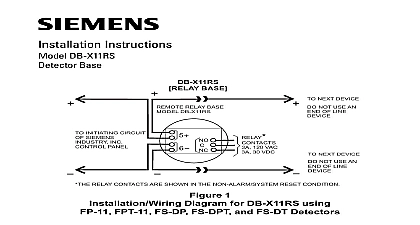
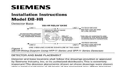
DO NOT AN OF NOT AN OF NOT AN OF NOT AN OF INITIATING OF INC UNIT 1 2 Instructions DB 11 11E 8853 11C DETECTOR BASE NO REMOTE DEVICE REMOTE DEVICE INSTRUCTIONS FOR WIRING DETAILS INITIATING UNIT CAUTION 1 REMOTE RELAY BASE RLW 11 RSAW 11 8849 8848 TION 315 094924 315 094925 315 094926 315 096162 315 095519FA 315 094925FA 315 094926FA OF LINE DEVICE POLARITY APPLICABLE Do not use looped wire under base terminal 5 Break run to provide supervision of connection When a remote relay is used to control a critical system function relay and its associated detector and optional module s be the ONLY devices on the initiating circuit 1 Wiring Diagram for DB 11 11E 8853 11C using PE 11 PE 11T DT 11 8854 8842 OP121 OH121 and HI121 Detectors NO REMOTE DEVICE REMOTE RELAY BASE NEXT BASE RLI 2 120 VAC 30 VDC 2 Wiring Diagram for DB 11 11E 11C using FP 11 FPT 11 FS DP FS DPT and FS DT Detectors NO REMOTE DEVICE REMOTE RELAY BASE NEXT BASE relay contacts are shown in the Non Alarm System Reset condition NEXT BASE INITIATING OF UNIT 120 VAC 30 VDC relay contacts are shown in the Non Alarm System Reset condition NEXT BASE FDO421 FDOOT441 FDOOTC441 FDOT421 FDT421 HI921 OH921 OOH941 OOHC941 and OP921 detectors are are polarity insensitive detectors 1 and Line 2 can be either line of the loop compatible with the DB HR or 8716 remote relay base SFP 11 Series detectors are approved for use in Canada only 3 Wiring Diagram for DB 11 11E 8853 11C using Series HFP 11 FDO421 FDOOT441 FDOOTC441 FDOT421 HI921 OH921 OOH941 OOHC941 OP921 SFP 11 and 8710 8711 8713 Detectors Industry Inc Infrastructure Park NJ Canada Ltd North Service Road Ontario 0H6 Canada Ltd No 16 8 Village 605009 India 500 094151 ID A6V10323391 Instructions P N 315 094193 15 that screw terminals are tight dress and position all wires flat against the base up all slack in the outlet box wires away from connector terminals insure proper installation of the detector head into the base jumper must be removed from each base prior to installing detector family devices Do not use a jumper for FP 11 HFP 11 FDO421 FDOOT441 FDOOTC441 FDOT421 FDT421 HI921 8842 detectors use DBJ 11 Jumper Kit P N 500 699167 between terminals 1a and 1b to complete the To allow for the continuity check with PE 11 PE 11T DT 11 OP121 OH121 HI121 8854 8843 all bases are installed check loop continuity Refer to the System Manual for the loop continuity check to the base terminals Refer to Figures 1 2 and 3 for details wires through the hole in the center of the base and mount base to outlet box Make connections ALARM LED viewing is critical position the LED mark in the base in the intended direction all wires outward from outlet box to Figures 4 and 5 as applicable on a 4 inch octagonal and SBG41 42 or equivalent MOUNTING The DB 11E Base 5 a 4 inch square a 4 inch octagonal and a single gang box AWG min AWG The detector is to be mounted for the number and size of conductors used Wire size boxes with the box size and depth required by the bases were designed to be mounted on the following AND DB 11C MOUNTING permitted for each circuit of detectors and restrictions on the use of remote are wired to the FDLC Note any limitations on the to the DLC S Series devices and 8710 8712 8713 to the DLC or FS DLC FDOT421 OH921 devices are of each control panel cover NOTE H Series devices are the wiring connection drawing installed on the inside shown in Figures 1 2 or 3 and wired to the control panel Industry Inc s detectors should be interconnected WIRING Standard 72 and CAN ULC S524 of detector Installation Wiring Instructions and to drawings are not available refer to Detector Placement a careful evaluation of all facets of the protected area placements shown on these drawings were chosen distributors This is extremely important The or approved by Siemens Industry Inc or its and base locations shall follow the drawings AND BASE PLACEMENT India Village 605009 No 16 8 Ltd 0H6 Canada Ontario North Service Road East Canada Ltd Park NJ Infrastructure Industry Inc BASE WITH LED The DB 11 8853 11C Base 4 COVERS BASE WITH LED 500 094151 initiating circuit of compatible control unit BASE DB 11 DB 11E 8727C RL HC 1 2 NEXT BASE NOT USE AN OF LINE DEVICE 120 VAC 30 VDC NOT USE AN OF LINE DEVICE NEXT BASE The relay contacts are shown after System reset which represents the non alarm condition 4 Wiring Diagram for Class X Isolator mode Industry Inc Infrastructure Park NJ Canada Ltd North Service Road East Ontario L6H 0H6 Canada DB 11 11E 8853 500 094151 500 094151E