Siemens DFM DFM-BRK Fiber Optic Interface and Bracket for DNET, Installation Instructions

File Preview
Click below to download for free
Click below to download for free
File Data
| Name | siemens-dfm-dfm-brk-fiber-optic-interface-and-bracket-for-dnet-installation-instructions-6827513940.pdf |
|---|---|
| Type | |
| Size | 641.17 KB |
| Downloads |
Text Preview
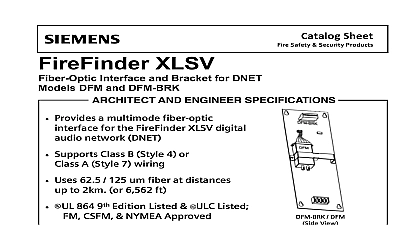
Installation Instructions DFM DFM BRK Optic Interface and Bracket For DNET Model DFM BRK from Siemens Industry Inc a fiber optic interface for the FireFinder XLS audio network DNET which interconnects the modules The DFM BRK can be connected Style 4 or Style 7 and utilizes the Telebyte model fiber optic converter The DFM uses 62.5 125 um at distances up to 2KM Standard ST connectors provided for connection of the optical fiber DFM BRK mounts in the rear of the XLS CAB 1 2 3 and occupies one module space 1 Fiber Optic Bracket For all system power before installation first battery then AC To power up the AC first then the battery DFM BRK requires at least one DFM converter Required DFM may be ordered P N 500 634910 Check the wiring section below and determine the quantity location of the DFMs for each DFM BRK in the system one of the DB 25 cables P N 555 134899 supplied with the to each DFM Secure the DB 25 connector using the screws are captive on the DFM the DFMs on the DFM BRK with the ST connectors facing the bottom the DFM BRK Be sure to observe the locations of the DFMs for the first last DAC NETs in a Style 4 network see Figure 2 These two locations only one DFM and their location on the DFM BRK is critical to proper operation 315 033779 6 Inc Inc Inc Industry Inc Inc TTTTTececececechnologies Di Di Di Division Di the DFM hold down bracket over the DFMs see Figure 1 and secure place using the two screws and nuts provided in the DFM BRK hardware the 6 position connector on the end of the DB 25 cable into the receptacle on the DFM BRK Mount the DFM BRK in the back of the enclosure with the four screws the hardware kit Wire between the DFM BRK TB1 and the DAC NET see Figure 2 24V from TB4 on the PSC 12 to TB2 on the DFM BRK be sure to the correct polarity see Figure 3 the fiber optic cables to the DFMs The transmit T output on each must go to the receive R input on its partner DFM for proper opera power If the Power LED on the DFM BRK is not lit check the polarity the 24V input on TB2 Once all DFM BRKs are installed check the DNET for errors Refer to the fault LEDs on the DAC NETs Once all DNET fault LEDs are clear the is properly connected RATINGS RATINGS Industry Inc Technologies Division 315 033779 6 Industry Inc Technologies Division 315 033779 6 R R PSC 12 TB4 12 14 AWG NEXT MODULE 3 Input Power Wiring security disclaimer products and solutions provide security functions to ensure the secure operation of building comfort safety security management and physical security systems The security functions on these products and are important components of a comprehensive security concept is however necessary to implement and maintain a comprehensive state of the art security concept that is to individual security needs Such a security concept may result in additional site specific preventive to ensure that the building comfort fire safety security management or physical security system for your are operated in a secure manner These measures may include but are not limited to separating networks protecting system components user awareness programs defense in depth etc additional information on building technology security and our offerings contact your Siemens sales or department We strongly recommend customers to follow our security advisories which provide infor on the latest security threats patches and other mitigation measures http www siemens com cert en cert security advisories htm Industry Inc Technologies Division Park NJ Canada Ltd North Service Road East Ontario 0H6 Canada ID A6V10239120 315 033779 6