Siemens DLC Device Loop Card, Installation Instructions

File Preview
Click below to download for free
Click below to download for free
File Data
| Name | siemens-dlc-device-loop-card-installation-instructions-9618730254.pdf |
|---|---|
| Type | |
| Size | 710.75 KB |
| Downloads |
Text Preview
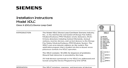
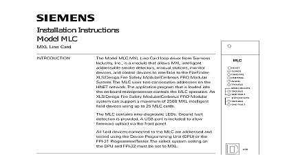
Installation Instructions DLC Loop Card Model DLC Device Loop Card from Siemens Industry is the interface for connection of FireFinder XLS Desigo Safety Modular Cerberus PRO Modular smoke detec Multi Criteria detectors including Carbon Monoxide stations monitor devices and control devices to the Fire Safety Modular Cerberus PRO System The DLC uses one network address on the The application program that is loaded into the on microprocessor controls the DLC operation DLC contains 12 LEDs for diagnosis of problems fault detection is provided by the loop field devices connected to the DLC are addressed and using the Device Programming Unit DPU FAIL FAIL FAULT STATUS A OPEN A RETURN A OPEN A RETURN DLC initializes operates and maintains all devices on the loop The DLC communicates all relevant and event information such as alarms and troubles the System CPU The sensitivity of any intelligent smoke and the logic functions of any intelligent output can be checked and adjusted from the Operator OI through the DLC All information about the on the loop can be displayed on the OI The DLC the System polarity insensitive devices to be without generating errors DLC supports only one loop two isolated parallel of up to 252 FireFinder XLS Desigo Fire Safety PRO Modular intelligent field devices as as device accessories relay bases audible bases and lamps in any combination The microprocessor the on board isolator to isolate either zone from loop if one of them is shorted When one zone is from the loop the other zone will still work on board microprocessor provides the DLC with the to function and initiate alarm conditions even if the FireFinder XLS Desigo Fire Safety Modular Cerberus Modular CPU fails 1 Device Loop Card 315 033090 17 Inc Inc Inc Industry Inc Inc TTTTTececececechnologies Di Di Di Division Di detectors Table 1 are supported by the OI FW version 9.02 and later the DLC with Firmware version 06 xx and later The DLC can be made backwards in systems using OI P N 500 033070 with DLC Firmware version 05.06 earlier OI collaborates with the DLC FW to identify compatibility with the Multi Criteria Table 1 In cases where the OI does not support the Multi Criteria the OI will specify Process Failure and illuminate the LED on the DLC In cases where Multi Criteria detectors are not used DLC can be reprogrammed with the FW version 05.06 or earlier The compatibil chart is as follows and Indicators front panel of the DLC contains one reset switch 12 LEDs and three HNET switches as shown in Figure 1 A reset switch is located on the top of the panel Pushing the reset switch re initializes the DLC operation LEDs follow the reset switch and their functions are defined as follows FAIL FAIL FAULT ON When illuminated indi the power for the DLC is applied to card OFF When illuminated indi the card microprocessor has failed OFF When illuminated indi that the HNET communication with DLC has terminated and the card into degrade mode OFF When illuminated indi that the DLC has detected either a or positive ground fault on its wiring OFF When illuminated indicates the DLC has detected an alarm OFF When illuminated indi that the DLC has detected a on its field wiring or incapability firmware in either the OI DLC both Industry Inc Technologies Division 315 033090 17 A OPEN 1 A RETURN 1 Yellow 1 A OPEN 2 A RETURN 2 Yellow 2 Off When illuminated indi a Zone 1 wire is open if the loop set to Class A Off When illuminated indi a Zone 1 return wire is reversed if loop was set to Class A Off When illuminated indi a Zone 1 wire short Off When illuminated indi a Zone 2 wire is open if the loop set to Class A Off When illuminated indi a Zone 2 return wire is reversed if loop was set to Class A Off When illuminated indi a Zone 2 wire short rotary dial switches at the bottom of the front panel are used to set the HNET address of the DLC All field devices connected to the DLC are addressed tested using the Device Programming Unit DPU Refer to the DPU Manual 315 033260 for further information Industry Inc Technologies Division 315 033090 17 the three digit HNET network address for the DLC using the three rotary dial located near the bottom of the front panel Refer to Figure 1 for the of the switches The address for the DLC must be the same as the address for it in the Zeus Programming Tool To set the address turn the pointers on of the three dials to the numbers for the selected address For example if the is 123 set the pointer for the HUNDREDS dial to set the pointer for the dial to and set the pointer for the ONES dial to The range of allowable is from 001 to 251 leading zeros must be used DLC plugs perpendicularly into one slot in the CC 5 card cage via two 96 pin DIN and can occupy any slot in the card cage Refer to Figure 2 the DLC card into the card guides rightside up on the front panel is legible the card in until the card edge connectors contact receptacles on the motherboard that the DIN connectors of the card and the card are aligned properly The card can only be plugged the card cage in one direction if it does not align NOT FORCE the card thumbs on the front panel adjacent to the captive and gently apply even pressure on the card until connectors seat in the receptacles on the the card with the captive screws 2 The DLC all system power before installation first battery then AC To power up the AC first then the battery field wiring to the DLC is connected to the terminal blocks of the CC 5 card cage in which it is installed Connect External Wiring the screw of the terminal by turning it counterclockwise the wire into the side of the terminal block the screw of the terminal block by turning it clockwise 24V from the PSC 12 to terminal 17 and 24V from the PSC 12 to terminal of the slot in the CC 5 where the DLC will be installed Refer to Figure 3 Industry Inc Technologies Division 315 033090 17 1 2 NOT USE SLOT OF CC 5 NOT USE 24VDC FROM THE PSC 12 3 The 24VDC Power Lines To The DLC Slot In The CC 5 ZONES MUST BE WIRED AS CLASS A ZONES MUST BE WIRED AS CLASS B A WIRING T TAPPING ALLOWED 1 2 B WIRING ALLOWED 1 2 OPTIONAL IN ENCLOSURE THE DLC TERMINATE ONE END ONLY