Siemens FCA2016-U1 RS485 class A module (isolated), Installation Instructions

File Preview
Click below to download for free
Click below to download for free
File Data
| Name | siemens-fca2016-u1-rs485-class-a-module-isolated-installation-instructions-9602875341.pdf |
|---|---|
| Type | |
| Size | 895.48 KB |
| Downloads |
Text Preview
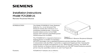
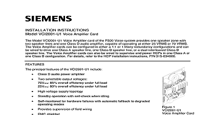
FCA2016 U1 class A module isolated Infrastructure notice notice specifications and availability subject to change without notice reproduction dissemination and or editing of this document as well as of its contents and communication thereof to others without express are prohibited Offenders will be held liable for payment of damages All created by patent grant or registration of a utility model or design patent are by Industry Inc Infrastructure Fernwood Road Park NJ 07932 1 973 593 2600 2019 11 25 ID A6V10334252 e en Siemens Industry Inc 2012 12 of contents class A module iso FCA2016 Mounting Wiring X2 data Statement 12 12 class A module iso FCA2016 RS485 class A module iso FCA2016 Description RS485 class A module iso FCA2016 is plugged into the PMI mainboard and is for operating periphery devices on the RS485 circuit e g the remote module FCA2018 for the external event printer PAL1 or the remote display and remote terminal FT2015 RS485 module has the following features Dual standardized RS485 interface Supports class and class Up to eight devices per RS485 class A module isolated Electrical isolation between the RS485 interfaces and the panel Supervised for ground fault Mounting RS485 class A serial module iso FCA2016 must be installed in the specified in the operating unit Mounting is the same for each slot the RS485 module has been pre configured in the Desigo Fire Safety Works the address must be assigned accordingly to the slot 12 class A module iso FCA2016 1 Slots for serial modules in the operating unit module in first slot X14 module in second slot X19 2 Installation of the serial modules 12 class A module iso FCA2016 links on support plate fixing screw class A module iso terminal on RS485 module X19 Slot for RS485 module Plug the serial module into the corresponding male connector first module into second module into X19 Fasten the serial module to the fastening tabs 1 using the two screws 2 Wire the serial module with the appropriate assemblies according to the pin will find more information about the wiring in document A6V10334278 DIN rail See chapter Applicable documents Views 3 Printed circuit board view of RS485 class A module isolated FCA2016 connection to the operating unit rear panel terminal for RS485 interface Wiring Plug X2 Circuit A feed 12 class A module iso FCA2016 Circuit B feed Circuit A return Circuit B return size 12 diagram RS485 network B 4 Wiring diagram FCA2016 class Supervised for ground fault open circuit and short circuit Length of class circuits must not exceed the maximum of 65 20 Class B circuits must be terminated with 120 Observe polarity for circuits and B Power limited acc to NFPA 70 NEC 760 Ground faults detected at 1 All wiring in accordance of article 760 of NEC or local building code A 5 Wiring diagram FCA2016 class 12 class A module iso Fire system panel24 V AUX BRARBFAFFCA2016FT2014 FT2015X6NET INX5NET OUTFT2014 FT2015X6NET INX5NET OUTFCA2018for PAL 1 printerMaximum of 8 modules in any configuration allowed21X234RS485 class A module iso Fire system panel24 V AUX BRARBFAFFCA2016Maximum of 8 modules in any configuration allowedFT2014 FT2015X6NET INX5NET OUTFT2014 FT2015X6NET INX5NET OUTFCA2018for PAL 1 printerfirealarmresources com input circuit class A module iso FCA2016 data Class must not exceed the maximum length of 3940 including return Observe polarity for circuits A and B Ground faults detected at 1 will find details of wiring for the modules on the RS485 circuit in the descriptions the corresponding modules Technical data current Standby Alarm of participants length per class circuit length per class circuit class resistance line to line capacitance isolation between the RS485 and the panel for gauge 75 136 at 100 including line Ground fault at 1 to ground Interruption Short circuit 12 Statement FCC Statement and usage of equipment is not in accordance with instructions manual of radio frequency energy to radio communications Install and use equipment in accordance with instructions manual Read the following information equipment generates uses and can radiate radio frequency energy and if not and used in accordance with the instructions manual may cause interference radio communications has been tested and found to comply with the limits for a Class computing device to Part of FCC which are designed to provide reasonable protection such interference when operated in a commercial environment of this equipment in a residential area is likely to cause interference in which the user at his own expense will be required to take whatever measures may be to correct the interference 12 12 Siemens Industry Inc 2012 specifications and availability subject to change without notice by Industry Inc Infrastructure Fernwood Road Park NJ 07932 973 593 2600