Siemens FCA2032-U1 Battery Disconnect Module, Installation Instructions

File Preview
Click below to download for free
Click below to download for free
File Data
| Name | siemens-fca2032-u1-battery-disconnect-module-installation-instructions-7216435890.pdf |
|---|---|
| Type | |
| Size | 700.08 KB |
| Downloads |
Text Preview
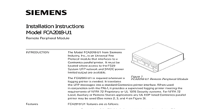
INSTALLATION INSTRUCTIONS FCA2032 U1 Disconnect Module model FCA2032 U1 Battery Disconnect Module from Siemens Industry Inc is designed to disconnect backup battery when its voltage drops below 19VDC This prevents the battery from discharging pass point where system operation cannot be guaranteed The battery remains disconnected until AC is restored to the system The module shares its mounting location with FCA2015 U1 DACT see Figure 1 In order for the BDM to connect to the battery set to the system the terminal voltage of the battery must be at least 21VDC Battery sets with lower terminal voltages must be replaced in order for the to recognize that a healthy battery set is present is to be done by qualified personnel only and trained in proper operation of the FS20 systems the steps below to install FCA2032 U1 Remove the power from the panel by first disconnecting the backup battery and then the AC FCA2015 U1 DACT module is present in the system it must be installed first prior to the of the FCA2032 U1 Battery Disconnect Module using the standoffs provided with the If no dialer is present then skip to step 3 Using the 4 standoffs install the mounting plate onto the back box Cut the battery cable to the proper length to allow enough length to reach from the Periboard and Strip the wire 3 8 of an inch 10mm to allow connection to the FCA2032 U1 Connect the Periboard battery Connection X303 to J1 of FCA2032 U1 while observing proper batteries polarity Industry Inc Technologies Division Park NJ A6V10385200 b en Connect the FCA2032 U1 Battery Connection J2 to the battery observing the proper voltage Connect FCA2032 U1 J7 to Aux Power connection of the Periboard X1001 observing proper polarity A6V10385200 b en Dress the wiring with consideration to power limited the dashed line from Aux connector non limited the solid line from battery connections separation as shown in Figure 1 Activate the panel by connecting AC power and then the battery 1 FCA2032 U1 Installation Location Verify that the battery gets connected to the system provided that the battery voltage is greater 21VDC the fuse on the Periboard blows then check the wiring from the Periboard to the FCA2032 U1 the panel reports a Battery trouble then check the polarity of the wiring from the to battery AUX Power all the wiring appears to be correct but the panel still reports a Battery trouble then the voltage across the batteries If the voltage is not above 21 VDC then the FCA2032 will not connect them to the panel Remove the batteries from panel and charge batteries until the voltage is above 21VDC or replace with a new set that meets the voltage A6V10385200 b en size Cutoff Data 5 8 x 3 5 8 49 32 120 19VDC 24VDC max Power 24VDC when AUX Power is while the system is battery 28VDC Rating A6V10385200 b en A5Q00054385