Siemens FDBZ492-PR Global Air Duct Monitoring Housing, Installation Instructions

File Preview
Click below to download for free
Click below to download for free
File Data
| Name | siemens-fdbz492-pr-global-air-duct-monitoring-housing-installation-instructions-7129354068.pdf |
|---|---|
| Type | |
| Size | 709.81 KB |
| Downloads |
Text Preview
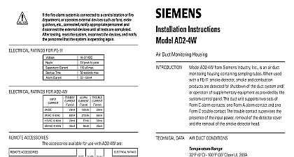
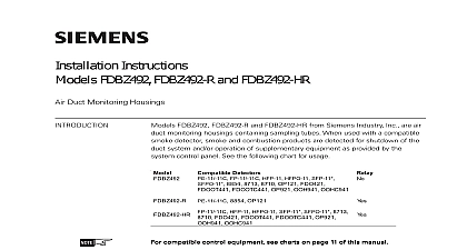
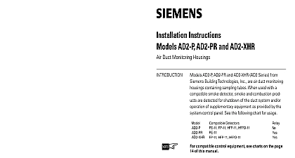
Installation Instructions FDBZ492 PR Air Duct Monitoring Housing DATA DUCT CONDITIONS FDBZ492 PR from Siemens Industry Inc is a RoHS air duct monitoring housing containing sampling When used with a Siemens conventional smoke detector and combustion products are detected for shutdown of duct system and or operation of supplementary equipment provided by the system control panel The duct unit supports sets of Form C alarm contacts one Form A alarm contact one Form C trouble contact The trouble contact supervises presence of the input power removal of the detector cover the removal of the smoke detector head Range PE 11 8854 PE 11C 0OC 32OF 38OC 100OF OP121 0OC 32OF 49OC 120OF Range altitude limitations Humidity to 95 RH non condensing non freezing Duct Velocity Range ft min and Exhaust Tube Pressure Differential Range than 0.01 and less than 1.2 inches of water column and and detectectectectection and det det are designed for are designed for duct det duct det air air and are designed for det duct detectors are designed for air duct det and det are designed for duct det air air are are in a duct systststststem em em em em They are in a duct sy in a duct sy of products of combust of products of combust are of products of combustion in a duct sy are in a duct sy of products of combust of products of combust open area protectectectectection open area prot open area prot for for to be used as a substitititititututututution for to be used as a subst to be used as a subst for open area prot open area prot for to be used as a subst to be used as a subst VVVVVerificat with with duct det duct det USE air USE air NO NO with Alarm duct detectors with USE air duct det NOT USE air with duct det USE air NO NO detector has a cover tamper removal switch Care should taken when installing the cover Squarely place the cover on unit to aviod possible damage to the switch POSITION POSITION INTTTTTO POSITION IN IN NO NO SLIDE CO SLIDE CO POSITION SLIDE COVER IN NOT SLIDE CO POSITION IN SLIDE CO NO NO A6V10330327 a en Inc Inc Inc Industry Inc Inc TTTTTececececechnologies Di Di Di Division Di FDBZ492 PR duct smoke detectors provide early detection smoke and products of combustion present in air moving an HVAC duct supply return or both These devices are to prevent the recirculation of smoke in areas by the handling system fans and blowers and may be used with alarm systems that shut down complete air handling system the event of smoke detection the cor the cor the cor inst inst of a duct smok of a duct smok unit please refer unit please refer of a duct smoke unit please refer of a duct smok installat the correct inst unit please refer of a duct smok inst the cor unit please refer NFP NFP 72 Nat 72 Nat Fire Fire Code Code NFP NFP 90A St 90A St 90A Standard Fire Alarm Code NFPA 90A St Code NFP 72 National Fire NFPA 72 Nat 90A St 72 Nat NFP NFP Code Fire NFP of AirAirAirAirAir Condit Inst Inst Inst and and S Syyyyystststststems of of Condit Condit and VVVVVentententententilat S S of Conditioning and Installat and of Inst Condit S NFP NFP 92A R 92A R Smok Smok P P for for Control Control Smoke Control for Smok for Pract 92A Recommended P NFPA 92A R Control NFP Smok for P 92A R NFP Control unit is not intended for open area protection nor should it used for early warning detection or to replace a regular fire system the Model FDBZ492 PR is operating a sample of air is from the duct and passed through the sampling chamber by of the input sampling tube The air sample passes through smoke detector mounted in the duct housing and is exhausted into the duct through the outlet tube FDBZ492 PR supports two sets of Form C alarm one Form A alarm contact and one Form C trouble The trouble contact supervises the presence of the power removal of the detector cover and the removal the smoke detector head FDBZ492 PR contains a green power on LED red alarm and yellow trouble LED which are visible through the cover trouble LED is activated when either the housing cover smoke detector is removed from the unit When the trouble LED is activated the power LED turns off reset test switch is located on the housing cover and is to reset the unit after an alarm and the smoke is cleared When not in alarm the reset test can be used to test that the unit will operate when an alarm condition exists trouble contacts will not operate in the event of a smoke alarm FDBZ492 PR duct detector will operate from various input sources namely 24VAC 24VDC 115VAC and 230VAC Industry Inc Technologies Division A6V10330327 a en LED FDBZ492 PR contains an LED indicator located on the detector capable of flashing either one of three distinct green yellow or red During each flash interval the based detector checks the following smoke in its sensing chamber its critical smoke sensing electronics are operating on the results of these checks the LED indicator flashes follows guideline contains general information on duct smoke installation but does not preclude the NFPA docu listed Siemens Industry Inc assumes no responsibility improperly installed duct detectors To determine the correct position for an FDBZ492 PR duct smoke detector the factors must be considered A uniform non turbulent laminar airflow between 100 ft to 5,000 ft min must be present in the HVAC duct To duct velocities examine the engineering that define the expected velocities or use an model 6000AP velocity meter or equivalent minimize the impact of air turbulence and stratification performance a duct smoke detector should be located far as possible downstream from any obstruction i e plates elbows dampers etc In all situations THE AIR DUCT HOUSING on Duct System Industry Inc Technologies Division A6V10330327 a en of velocity and pressure differential within is required pressure differential between the input sampling high tube and outlet low pressure tube for the smoke duct detector should be greater than inches of water and less than 1.2 inches of water a code compliant location supply or return side or for the installation of the duct unit that will permit access for viewing and serviceability When installing on the return side install duct units prior to air being exhausted from the building or diluted with air When installing duct smoke units downstream of filters occurring in the filters will be detected but if the filters blocked insufficient air flow through the duct unit prevent the correct operation of the duct detector Duct installed in the supply air side may monitor upstream and or filters DUCT