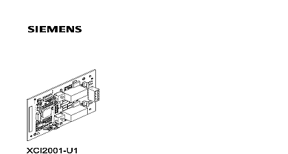
Siemens FN2001-U1 Network module (SAFEDLINK), Installation Instructions

File Preview
Click below to download for free
Click below to download for free
File Data
| Name | siemens-fn2001-u1-network-module-safedlink-installation-instructions-5890372164.pdf |
|---|---|
| Type | |
| Size | 1.03 MB |
| Downloads |
Text Preview
FN2001 A1 module SAFEDLINK Industry Inc Technologies Division notice notice specifications and availability subject to change without notice Siemens Industry Inc 2015 reproduction dissemination and or editing of this document as well as of its contents and communication thereof to others without express are prohibited Offenders will be held liable for payment of damages All created by patent grant or registration of a utility model or design patent are by Industry Inc Technologies Division Fernwood Road Park NJ 07932 1 973 593 2600 2015 04 16 ID A6V10315042 f en Industry Inc Technologies Division of contents module SAFEDLINK FN2001 4 4 5 the shielding 6 7 assignments 7 X3 7 data 10 Statement 11 Industry Inc Technologies Division module SAFEDLINK FN2001 Network module SAFEDLINK FN2001 Description network module FN2001 SAFEDLINK is used to network several via the system FCnet C WEB FN2001 may only be used for networking in a fire detection network module is plugged onto the PMI mainboard and has the following Connections for a system bus input and a system bus output Electrical isolation between the system bus and the panel Ground fault supervision Signal transfer in the event of line trouble caused by redundant networking with degraded mode function with signal transfer in the event of line trouble network module per panel Industry Inc Technologies Division module SAFEDLINK FN2001 Installation network module SAFEDLINK FN2001 must be installed in the left slot X13 module slot the network module SAFEDLINK FN2001 tabs on operating unit for screwed cable gland 2 per module 1 gland 2 per module 1 fixing screw module SAFEDLINK on X13 master module or C WEB SAFEDLINK connection terminal terminal on PMI mainboard When using shielded cables the cable glands are needed to secure the shielding sure you install the network module SAFEDLINK in the correct position plug during installation Industry Inc Technologies Division module SAFEDLINK FN2001 the shielding When shielded cables are used mount the two cable glands 3 with the nuts 2 the flange between the fastening tabs 1 Plug the network module SAFEDLINK 5 into the connector X13 as shown Fasten the network module to the fastening tabs 1 using the two fixing screws 4 Check that the network module is secured correctly in order to prevent open Wire up the system bus SAFEDLINK according to the pin assignment Installing the shielding using shielded cables the cable gland must be fitted the shielding element sleeve part of cable gland of contact sleeve Pull nut 1 sealing element 2 and contact sleeve 3 over cable Trim outer cable surround to the desired length Trim braid or shield film to the contact sleeve X length Slide nut 1 sealing element 2 and contact sleeve 3 to end of surround Place braid or shield film over contact sleeve 3 Cut off protruding material Guide the prepared cable into fitted bottom part of cable gland 4 until sealing 2 and contact sleeve 3 are flush in bottom part Screw nut 1 to bottom part such that the cable is firmly pressed in Industry Inc Technologies Division module SAFEDLINK FN2001 Views module SAFEDLINK FN2001 to the PMI mainboard connector on rear panel to the FCnet C WEB circuits connector on rear not used with FS20 FS920 to FCnet C WEB circuits used with FS20 FS920 green Status display for network module yellow Status display for circuit 2 yellow Status display for circuit 1 Pin assignments Connector X3 1 1 2 2 cable cross section 12 AWG Industry Inc Technologies Division module SAFEDLINK FN2001 assignments for class A network A SAFEDLINK wiring 1 2 n n module modules module for class B network B SAFEDLINK wiring 1 2 n module modules module Ground fault detected at 1 k Power limited acc to NFPA 70 NEC 760 No EOLR required Connect shields at one end only Max length of SAFEDLINK wiring between two modules 3300 ft 1005 m or 10 dB loss at 100 kHz 3300 ft 1005 m or 30 dB loss at 1 MHz All wiring is supervised for open circuits and short circuits will find detailed instructions on configuring the class A and class B SAFEDLINK in the following documents A6V10315023 for Desigo A6V10333423 for Cerberus PRO Industry Inc Technologies Division module SAFEDLINK FN2001 H1 Green H2 H3 Indicators of the module of circuit 2 B2 of circuit 1 B1 module SAFEDLINK is defective condition H2 and H3 are off condition for degraded mode module H2 and H3 off condition on circuit 2 is OK on circuit 2 communication on circuit 2 condition on circuit 1 is OK on circuit 1 communication on circuit 1 Industry Inc Technologies Division module SAFEDLINK FN2001 data Technical data bus SAFEDLINK type Shielded capacitance capacitance type Unshielded capacitance rate in operation mode between two network modules isolation between FCnet C WEB and for 24 V 35 mA 35 mA 5 V nF loop resistance 20 nF loop resistance 180 nF loop resistance 20 nF loop resistance 180 nF loop resistance 20 nF loop resistance 180 UDP IP kbit s kbit s 3300 ft 1005 m kV Short circuit Open circuit Ground fault Communication error AWG connection gauge unit Industry Inc Technologies Division Statement FCC Statement and usage of equipment is not in accordance with instr


