Siemens FP2013-U1 600W Power Supply Set, Installation Instructions

File Preview
Click below to download for free
Click below to download for free
File Data
| Name | siemens-fp2013-u1-600w-power-supply-set-installation-instructions-3540217689.pdf |
|---|---|
| Type | |
| Size | 751.98 KB |
| Downloads |
Text Preview
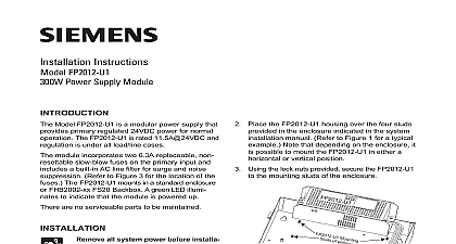
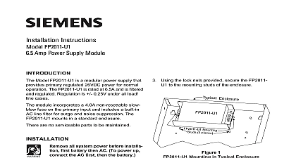
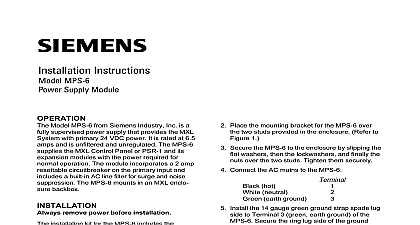
Mount the enclosure to the wall before mounting the FP2013 power supply to the enclosure Make sure that the dedicated circuit breaker for the unit is turned off at the mains Place both units over the mounting studs protruding from enclosure indicated in the system installation manual Figure 1 INSTRUCTIONS FP2013 U1 Power Supply Set Model FP2013 U1 is a cascaded power supply set of two individual supplies connected by an Current Share Cable It provides primary 24VDC power for normal operation The FP2013 is rated 20A 24VDC and regulation is under all load line module incorporates two 6.3A replaceable non slow blow fuses on the primary input and includes built in AC line filter for surge and noise suppression Refer Figure 4 for the location of the fuses The FP2013 U1 in a Voice 3HU enclosure A green LED illuminates to that the module is powered up are no serviceable parts to be maintained all system power before installation battery then AC To power up connect AC first then the battery installation kit for the FP2013 U1 includes the following Watt Power Supplies lock nuts Instruction Current Share Cable 240VAC installation reference the Selector Switch in Figure 4 before the FP2013 U1 module Industry Inc Technologies Division Park NJ Canada Ltd North Service Road East Ontario 0H6 Canada OF FCI2016 2017 BOARD X302 SUPPLY SECONDARY CABLES Current Cable Hot Black wire Neutral White wire Earth Ground Green wire For the second Position 2 power supply install a 3 power supply connector cable between the terminal on the first and second power supplies as shown Figure 1 Current Cable Replace the safety covers on the terminal blocks of the Power Supply Subassemblies 2 N G 1 N G MOUNTING 8 PLACES SUPPLY CABLE GROUND CONNECTION The Interconnect Current Share Cable provided in the is used to interconnect the wires attached to power supply subassembly refer to the Wire to Connector section Ensure the Jumper X305 located on Periphery Board is in position 2 and 3 Apply power only after all connections are complete Connectors Interconnect Current Share Cable provided in the kit the two power supply communication cables Figure 2 The Interconnect Current Share Cable assembly keyed and can only fit in one way BLOCK Figure 1 Mounting and Wiring the FP2013 U1 FP2013 is only available for 3HU FHB2005 Position 1 Connect Supply to X301 on Periphery Board Position 2 Connect Supply to X302 on the Periphery FCI2016 2017 Using the lock nuts provided in the installation kit secure FP2013 U1 s to the mounting studs on the FP2013 U1 is designed to operate from a 120 240VAC power source Use a separate or dedicated circuit for both supply units Wire in accordance with the having jurisdiction and Article 760 of the NEC NFPA latest edition Run the earth ground from a suitable source to each supply subassembly Check local requirements is not an acceptable earth ground conductor For each power supply subassembly to be installed the safety cover from the 3 position terminal and place it to one side Connect the AC mains to the 3 position terminal block on 1 power supply subassembly as shown in 1 Connect the mains to the terminal block as b 2 Interconnect Current Share Cable The Interconnect Current Share Cable MUST connected before power is applied RATINGS MAINS H N G Connector Current Cable Power SUPERVISED NON POWER LIMITED 18 AWG MIN 120 240VAC 120 VAC 3.0A max per unit 240VAC 1.5A max per unit 50 60Hz WITH CONNECTOR ON PERIPHERY BOARD 2 3 4 24VDC Regulated 20A max combined output of units Figure 3 FP2013 U1 Connections and regulated Temperature Range 49 32 120 F Use for indoor dry protected SELECTOR SWITCH FOR 240VAC all system power before installation battery then AC To power up connect AC first then the battery the AC input is 240VAC you will need to set the red selector switch on the side of the FP2013 U1 for each power supply to the 220VAC or 230VAC as shown in Figure 4 FUSES SWITCH 4 Selector Switch on the FP2013 U1 b page has been left intentionally blank Industry Inc Technologies Division Park NJ USA Canada Ltd North Service Road East Ontario 0H6 Canada ID A6V10436206 en b A5Q00062683