Siemens FT2008-U1 FT2008-R1 FT2009-U1 FT2009-R1 LED annunciator, Installation Instruction

File Preview
Click below to download for free
Click below to download for free
File Data
| Name | siemens-ft2008-u1-ft2008-r1-ft2009-u1-ft2009-r1-led-annunciator-installation-instruction-3109278465.pdf |
|---|---|
| Type | |
| Size | 985.39 KB |
| Downloads |
Text Preview
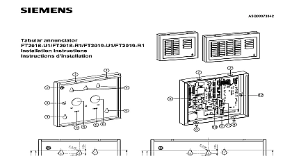
LED annunciator Instruction 11 11 9 FT2008 U1 FT2008 R1 FT2009 U1 FT2009 R1 For Canadian applications the are deemed supplementary and be used for display only It must be housed in a ULC S527 approved locked enclosure Not approved for UL ULC MNS applications Industry Inc Technologies Division use instruction FT2008 FT2009 LED annunciator enables the fire system to be displayed and operated in a way The FT2008 provides 2 LEDs to alarm trouble events The FT2009 provides 2 to display alarm trouble events Both devices are on the UFP line device complies with Part 15 of the FCC Rules is subject to the following two conditions This device may not cause harmful interference This device must accept any interference received interference that may cause undesired operation contents following are included in the scope of delivery FT2008 U1 FT2008 R1 or FT2009 U1 FT2009 R1 Cable ties 2 pcs EOL jumper connecter 1 pcs Break out the required cable openings 6 on the Mark the drilling points for the 3 mounting holes 4 drill holes and insert the anchors not supplied or use pre drilled mounting holes for installation on a 2 or 4 square standard electrical box Pull the cables for the UFP and power supply through breakout openings 6 on the backbox Screw the backbox tightly in place Connect the cable to the terminal 11 in accordance the connection diagram Configure Dip switch 8 and EOL jumper 10 Connect the green earth ground cable from front panel Hook the front panel with the holes 7 over the stubs 1 to backbox 3 the backbox Press the front panel down over the backbox screw 9 and fix the front panel in place Dip switch is used for setting address and baud rate first 1 4 digits are for setting address the 7 8 digits are setting UFP communication baud rate The 5 6 digits are for future use instructions of injury to persons and damage to property observe the following safety instructions The devices are only intended for stationary installation dry rooms The devices may only be connected to the UFP line If panel AUX power is not used an UL listed recognized fire use regulated power limited 24V DC power is required Static discharge precautions should be taken when the FT2008 FT2009 for mounting cover 2 pcs Shield terminal Earth ground terminal Mounting holes 8 pcs Cable tie point Breakout openings for cables 2 pcs Holes for hanging front panel over stub 2 pcs Dip switch Screws 2 pcs EOL jumper Connection terminals for UFP line and power supply Front panel earth ground connection Off Off Off Off On Off Off On Off Off Off On Off Off On Off Off On On Off On On Off Off Off On data W x H x D inch temperature temperature voltage Rate bps bps On bps Off bps On lb lb rel DC Nominal DC current current mA mA mA mA Siemens Industry Inc specifications and availability subject to change without notice by Industry Inc Technology Division Fernwood Road Park NJ 08932 1 973 593 2600 No