Siemens GCM-8 Graphics Control Module, Installation Instructions
File Preview
Click below to download for free
Click below to download for free
File Data
| Name | siemens-gcm-8-graphics-control-module-installation-instructions-2197403658.pdf |
|---|---|
| Type | |
| Size | 628.22 KB |
| Downloads |
Text Preview
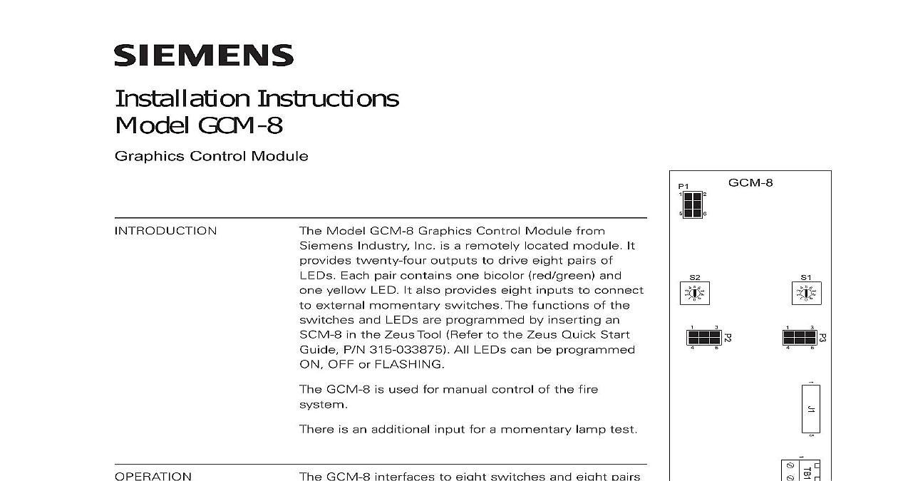
Installation Instructions GCM 8 Control Module Model GCM 8 Graphics Control Module from Industry Inc is a remotely located module It twenty four outputs to drive eight pairs of Each pair contains one bicolor red green and yellow LED It also provides eight inputs to connect external momentary switches The functions of the and LEDs are programmed by inserting an in the Zeus Tool Refer to the Zeus Quick Start P N 315 033875 All LEDs can be programmed OFF or FLASHING GCM 8 is used for manual control of the fire is an additional input for a momentary lamp test GCM 8 interfaces to eight switches and eight pairs LEDs Each switch is associated with a pair of LEDs any of the eight switches generates a unique message on the bus to the NIC C or DAC NET that which switch was pressed A CAN message the NIC C or DAC NET to the GCM 8 produces a output to the corresponding LED ON or OFF An open collector is provided for to the CAN Sounder Board CSB a separate module The CSB provides an audible feedback to that the switch closed properly and that between the GCM 8 and NIC C or was successful Refer to the CSB Installation P N 315 033040 for more information shorting terminals 1 and 2 of TB1 all LEDs will turn to confirm that they are working and automatically return to their normal state after a few seconds The test switch on multiple GCM 8s can be connected a single switch 5 6 5 6 1 Graphics Control 315 050637 2 Inc Inc Inc Industry Inc Inc TTTTTececececechnologies Di Di Di Division Di SWITCHES 5 6 5 6 the board address for each GCM 8 using both of the ten position rotary switches and S2 located on the board See Figure 1 The address must be a sub address the NIC C or DAC NET and must be the same as the addresses assigned in the Programming Tool To set the address turn the pointers on each of the dials to numbers for the selected address For example if the address is 12 set the for the TENS dial S1 to and set the pointer for the ONES dial S2 to range of allowable addresses is from 01 to 99 leading zeros must be used GCM 8 may be installed in a REMBOX When using REMBOX 2 or 4 mount the in one module space on a REMBOX2 MP P N 500 634211 or REMBOX4 MP 500 634212 using the four screws provided Refer to REMBOX2 MP REMBOX4 Installation Instructions P N 315 034211 Up to 4 GCM 8s will fit in a REMBOX2 to 8 GCM 8s will fit in a REMBOX4 all system power before installation first battery then AC To power up the AC first then the battery GCM 8 module is a node in the CAN bus GCM 8 can be installed with or without an RNI Connect 24V and CAN as shown in Figure 2 to 99 CAN modules in any combination can be connected to the CAN of each NIC C or DAC NET GCM 8 module is shipped with one CCS cable connections for GCM 8 modules are shown in the following table CAN bus requires a 120S resistance at each end of the loop Refer to the NIC C Instructions P N 315 033240 for details about CAN termination Industry Inc Technologies Division 315 050637 2 to J2 are shown in the following table GCM 8 has 2.7K limiting resistors for the Yellow1 to Yellow8 LEDs The 2.7K resistors for the bicolor LEDs must be provided by the External Graphics Industry Inc Technologies Division 315 050637 2 CCS 5 6 5 6 P3 ON P4 RNI CCL TERMINATOR 110 134215 WITH NIC C 5 6 5 6 All wiring must be in with Article 760 NEC or local building All circuits are power limited article 760 of NEC Electrical Ratings current 14mA max 24VDC current 200mA 24VDC For additonal information to the NIC C Installa Instructions P N 315 Lamp test switch must be 864 listed devices CAN network max line 15S Mount the Lamp Test on the front door P1 and J1 are for factory use CABLE BE PROVIDED EXTERNAL PANEL FOR CONNECTION TO GEO LINE UP PIN 1 J2 WITH PIN MARKED 1 IN GEO PANEL 2 Wiring RATINGS Industry Inc Technologies Division Park NJ Canada Limited Technologies Division Kenview Boulevard Ontario L6T 5E4 Canada 315 050637 2